Typical Underground Cable Arrangements
Found 8 free book(s)
POWER CABLE INSTALLATION GUIDE - Anixter
www.anixter.comTYPICAL CALCULATION FOR CABLES IN CONDUIT 23 CABLES BURIED DIRECTLY IN EARTH 28 ... Some of the equipment and arrangements used to install cable are illustrated in the following figures: a) At the feed-in, the curvature of the cable feed is in the same continuous ... 1 IEEE 532-1993 “Guide for Selecting and Testing Jackets for Underground ...

Technical Specification for Secondary Substation Earthing
www.spenergynetworks.co.ukScenario (1) - Dense large urban network (e.g. Cities and large towns) - all underground modern cable ... arrangements are permitted by those documents and/or where further information is required. ... These are standard designs of typical ground-mounted substations and

Utility Installation Guide: Electricity - Energetics
energetics-uk.comcable tube 32mm dia to E.S.I. tech spec 12-24 Note: Floor Construction May Vary 90 600 min round Level 600 min 2000mm Typical 275mm cavity wall construction round Level 150mm Tube in position Cable entry performed from a length of 32 inside diameter whitered high impact rigid P.V.C tubing • Example arrangements for external meter box

WA Electrical Requirements
www.commerce.wa.gov.au3.4 Point of Supply (Underground Low Voltage) 3.4.1 Standard Domestic Connection Typical point of supply arrangements for domestic connections are illustrated in the Figures below. In particular, the following principles apply: 1) A network operator’s service pillar on a lot is the point of supply for that lot and (in most cases)
Electric Power Distribution Systems - EOLSS
www.eolss.netA typical customer substation in a ring-configured network contains two feeders and one transformer feeder. The former have circuit breakers and cable connecting to other substations while the latter has circuit breaker and cable connecting to 11kV/LV transformer. A typical ringed network arrangement is shown in Figure 2. Figure 2.
Work near underground assets – Guide - SafeWork NSW
www.safework.nsw.gov.auWORK NEAR UNDERGROUND ASSETS – GUIDE 5 8.5 Provision of information and instruction 47 9. Case studies and check lists 48 9.1 Repairing sewerage pipes 48 9.2 Country telecommunications cable damage case study 49 Site observations 49 9.3 City telecommunications cable damage case study 50 9.4 Example of an Incident Report
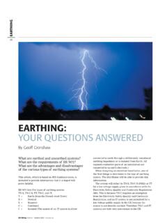
EARTHING - IIT Bombay
www.ee.iitb.ac.inFig 2:Cable sheath earth (TN-S system). Schematic of earthing and main equipotential bonding arrangements. Based on 25 mm2 tails and selection from Table 54G. Note: An isolator is not always installed by the electricity distributor. Fig 1:TN-S system
CHAPTER 9 TRAFFIC SIGNAL DESIGN – SUPPORTS AND …
www.tn.govpossible, diagonal span wire layouts should always be avoided. Typical strain pole span wire layouts are shown in Figure 9.1. The following are the most common span wire arrangements: • Box Span Arrangement: This signal arrangement is the most common and places strain poles on each of the four corners of the intersection. Advantages: