Valve Position
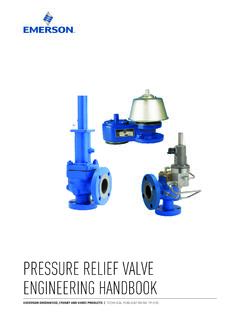
Found 6 free book(s)PRESSURE RELIEF VALVE ENGINEERING HANDBOOK
www.emerson.comB. Full lift PRV: a pressure relief valve in which the actual discharge area is not determined by the position of the disc. C. Reduced bore PRV: a pressure relief valve in which the flow path area below the seat is less than the flow area at the inlet to the valve. D. Full bore PRV: a pressure relief valve in which the bore area is equal
Catalog HY14-2500/US Directional Control Valves Technical ...
www.parker.comHydraulic Valve Division Elyria, Ohio, USA Catalog HY14-2500/US Directional Control Valves A General Description Series D1VW directional control valves are high performance, 4-chamber, direct operated, wet armature solenoid controlled, 3 or 4-way valves. They are available in 2 or 3-position and conform to NFPA’s D03, CETOP 3 mounting ...
INS2153C - 6/14
assets.moen.comRemove valve and reinstall in the proper orientation Restricted temper-ature range Handle (more common in knob models) is installed upside down In the off position, able to turn the handle both clock-wise and counterclockwise Remove handle, rotate 180˚, re-install Temperature limit stop out of position Remove handle and see Step 5.3 Position ...
69-2698EFS-03 - FocusPRO® TH5000 Series
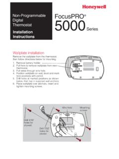
customer.honeywell.comPosition wallplate on wall, level and mark hole positions with pencil. 5. Drill holes at marked positions as shown below, then tap in supplied wall anchors. 6. Place wallplate over anchors, insert and ... 1 Changeover valve (O/B terminal energized in heating) 3 Fan control (heating)
Vickers Pressure Relief Pressure Relief Valves
www.eaton.comrecommended for controlling this valve. Figure 2 shows the basic diagram (amplifier switch should be in position 1). 12 11 10 9 8 7 6 5 4 3 2 1 +12V 5K 1W Pot 115V 60 Hz Valve Coil EMCS-*-30 Power Supply Figure 2 Tank Connection The tank connection should be piped directly to tank through a surge free line to minimize back pressure. If tank line
Dear Imaging Center - .NET Framework
edwardsprod.blob.core.windows.netrelatively close to the position of these devices. Optimization of MR imaging parameters is recommended. The valve wireform stent is composed of a corrosion-resistant cobalt-chromium spring alloy that is commonly used in implantable devices. The nominal composition (wt. percent) is …


