Vent Relief Valve 1 8 1
Found 8 free book(s)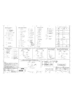
MISCELLANEOUS SYMBOLS: VALVE ACTUATORS
www.hanford.govnote 1 note 1 open close travel fault note 2 (where applicable) xx valve fail action as per p&id note 1, 3 note 1 open close travel fault valve fail action as per p&id xx vent vent pressure or vacuum relief (angle pattern) flow meter pressure sensor pressure sensor vacuum relief detail 1c: modulating pneumatic actuated, dcs / plc control notes ...
Pressure Relief Device Inspection
www.dir.ca.gov1 . Purpose of Pressure Relief Devices • Last line of defense against overpressure ... Inspect pressure relief device nameplate data • Set pressure for single device ... • Bellows valve bonnet vent not plugged • No leakage through bonnet vent Device Condition 18 . No test gag!

K J I H G F E D C B A 1 V Vibration Valve
www.energy.gov12/8 0 4 sheet 1 of 6 scal e n o e d rwn by c. a sugh p tfo m v 2 01 pr fu li enam ... pressure r educing valve two way pressure relief three way pressure relief equipm nt fi ter pum dryer hy rogen c mp re s s tor ag nk ... 3/8"-h-15000psi 3/4"-h-vent of-802 to common ¾” vent mast located on back of gmp
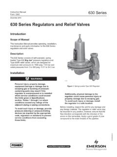
December 2015 630 Series Regulators and Relief Valves
www.emerson.comSpring Case Vent 1/4 NPT Material Temperature Capabilities(1) Standard:-20 to 180°F / -29 to 82°C Optional:-20 to 300°F / -29 to 149°C Orifice Sizes 1/8, 3/16, 1/4, 3/8 or 1/2 in. / 3.18, 4.76, 6.35, 9.53 or 12.7 mm Coefficients for Relief Valve Sizing ORIfICE SIzE C g V 1 In. mm 1/8 3/16 1/4 3/8 1/2 3.18 4.76 6.35 9.53 12.7 13.9 31.3 55.1 ...
PRESSURE RELIEF VALVE ENGINEERING HANDBOOK
www.emerson.com1.1 The primary purpose of a pressure or vacuum relief valve is to protect life and property by venting process fluid from an overpressurized vessel

The PERFORMANCE atmospheric gas water heaters feature …
images.thdstatic.comVent Size E Water Conn. Center F Ht. to Side T&P Valve G Water Conn. Size H Ship Weight (LBS) Uniform Energy ... Natural Gas Tall 55 55 XG55T06EC50UO† 50 51 97 59-1/8 55-7/8 23-3/4 14-1/4 4 8 48-3/4 3/4 175 0.62 ... 1/2" 3/4" N.P.T. RELIEF VALVE OPENING FLUE ANODE ROD E A B C F H HOT WATER CONNECTION H COLD WATER CONNECTION D 1/2" FLUE …

ALARM VALVE - NAFFCO FZCO
www.naffco.comCONSTANT PRESSURE TRIM FOR ALARM VALVE 1 # 2 2 16 13 15 14 10 8 12 2 1 1 6 3 5 3 7 2 4 16 15 14 24 25 NO NC NO NO 2 21 23 # D 22 11 17 10 9 18 19 26 D 19 27 30 29 28 29 2,29 2 1,28 17 28 1,28 28 20 D 26 GROOVE X GROOVE FLANGE X GROOVE FLANGE X FLANGE # # * Optional Trim Drain To suit at site by installer Normally Open Normally Closed Notes When ...
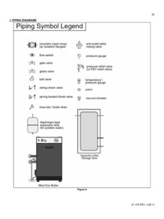
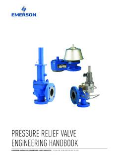
I. PIPING DIAGRAMS
www.htproducts.com24 LP- 276 REV. 3.28.14 Figure 8 NOTES: 1. This drawing is meant to demonstrate system piping concept only. Installer is responsible for all equipment and detailing required by local codes.