Voltage mode
Found 6 free book(s)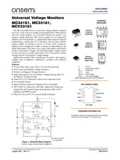
MC34161 - Universal Voltage Monitors
www.onsemi.com• Unique Mode Select Input Allows Channel Programming • Over, Under, and Window Voltage Detection • Positive and Negative Voltage Detection • Fully Functional at 2.0 V for Positive Voltage Sensing and 4.0 V for Negative Voltage Sensing • Pinned Out 2.54 V Reference with Current Limit Protection • Low Standby Current

Spektrum SmartLink ESC Programming App Instructions
www.horizonhobby.comBEC Voltage - Select the BEC output voltage. Default and available settings per ESC. Start-up Mode o Normal Start-up: If this mode is selected, the motor will immediately increase in RPM to correspond to the throttle stick input. o Soft Start-up: If this mode is selected, the motor will gradually increase in RPM to

MT-041: Op Amp Input and Output Common-Mode and ...
www.analog.comOUTPUT COMMON-MODE VOLTAGE RANGE . Figure 1 below is a general illustration of the limitations imposed by input and output dynamic ranges of an op amp, related to both supply rails. Any op amp will always be powered by two supply potentials, indicated by the positive rail, +VS, and the negative rail, –VS. We will define
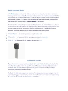
Bipolar Transistor BJT - University of Pittsburgh
sites.pitt.edumode of operation way back in their early days of development. There are two basic types of bipolar transistor construction, NPN. and . PNP, which basically describes the physical arrangement of the P-type and N-type ... It has a voltage gain that is always less than "1" (unity). The load resistance of the common collector transistor

LM339 - Single Supply Quad Comparators
www.onsemi.comInput Common Mode Voltage Range VICMR −0.3 to 36 Vdc Output Short Circuit to Ground (Note 1) ISC Continuous Power Dissipation @ TA = 25°C Plastic Package Derate above 25°C PD 1/R JA 1.0 8.0 W mW/°C Junction Temperature TJ 150 °C Operating Ambient Temperature Range LM239 MC3302 LM2901, LM2901E LM2901V, NCV2901 LM339, LM339E TA
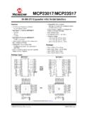
MCP23017/MCP23S17 Data Sheet - Microchip Technology
ww1.microchip.comMCP23017/MCP23S17 DS20001952C-page 6 2005-2016 Microchip Technology Inc. FIGURE 1-3: I2C BUS START/STOP BITS TIMING FIGURE 1-4: I2C BUS DATA TIMING TABLE 1-3: I2C BUS DATA REQUIREMENTS I2C Interface AC Characteristics: Unless otherwise noted, 1.8V VDD 5.5V at -40 C TA +125 C, RPU (SCL, SDA) = 1 k , CL (SCL, SDA) = 135 pF Param. No.