Waves And Impedances On Transmission Lines
Found 8 free book(s)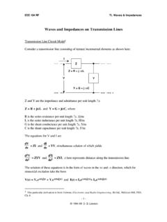
Waves and Impedances on Transmission Lines
home.sandiego.eduEEE 194 RF TL Waves & Impedances - 5 - wave reflecting from a dielectric or conducting boundary, transmitted and reflected waves are required to satisfy all the boundary conditions2. Waves can exist traveling independently in either direction on a linear transmission line.

15300 Soda Springs Rd., Los Gatos, CA 95030; The Story of ...
www.arrl.org20 QEX November/December 2018 half-wave 50 W transmission line is in place, an antenna impedance bridge can be used at the feed end on the ground to cut the …
A HIGH PERFORMANCE HALF-WAVE DIPOLE ANTENNA
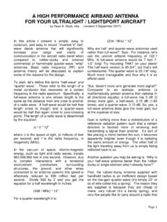
chrusion.comPage 1 A HIGH PERFORMANCE AIRBAND ANTENNA FOR YOUR ULTRALIGHT / LIGHTSPORT AIRCRAFT by Dean A. Scott, mfa (revision 3 September 2017) In this article I present a simple, easy to

Electrical measurements - folk.uio.no
folk.uio.no5 Some definitions relating to voltage and current Voltage and current Voltage, U, is the difference in electrical potential, φφφφ, between two locations: U = ∆φ = φ2 - φ1.The unit for voltage U is V (volt). Electrical field, E, is the negative of the gradient in electrical potential, i.e. it is defined to be directed from positive to negative pole: E = -dφ/dx.
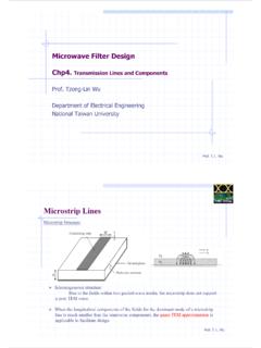
Prof. Tzong-Lin Wu Department of Electrical Engineering ...
ntuemc.twProf. T. L. Wu Discontinuities –Steps in width Note: L wi for i = 1, 2 are the inductances per unit length of the appropriate micriostrips, having widths W 1 and W 2, respectively. Z ci and ε rei denote the characteristic impedance and effective dielectric constant corresponding to width W i, and h is the substrate thickness in
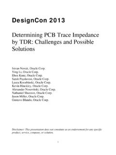
Determining PCB Trace Impedance by TDR: Challenges and ...
www.electrical-integrity.com1 DesignCon 2013 Determining PCB Trace Impedance by TDR: Challenges and Possible Solutions Istvan Novak, Oracle Corp. Ying Li, Oracle Corp. Eben Kunz, Oracle Corp.

Project 1: Rectangular Waveguide (HFSS)
www.rit.eduProject 1: Rectangular Waveguide (HFSS) r Objective • Getting Started with HFSS (a tutorial) • Using HFSS, simulate an air-filled WR-90 waveguide shown above. • To obtain the Field patterns, intrinsic Impedance and wavelength for the first 4 modes. Analysis 1.) Sweep from 4-20 GHz 2.) Analysis must include first three modes (TE10, TE20, TE01) 3.)
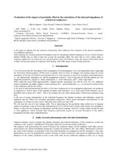
EVALUATION OF THE IMPACT OF PROXIMITY EFFECT IN THE ...
www.ursi.orgEvaluation of the impact of proximity effect in the calculation of the internal impedance of cylindrical conductors Alberto Pagnetti1, Alain Xemard1, Francoise Paladian2 , Carlo Alberto Nucci3 1 EDF R&D, 1, Av.du G.de Gaulle, 92141, Clamart, France - email : Alberto.pagnetti@edf.fr – Alain.xemard@edf.fr