Transcription of Hydraulic Calculations for - Igneus Inc
1 Hydraulic Calculations for Project: Your First System version 2. Drawing no.: Date: 10/16/2009. Design Remote area number: Remote area location: Hydraulically most remote Occupancy classification: ordinary hazard group II. Density: Area of application: 1500 Coverage per sprinkler: 100 Type of sprinklers calculated: Standard 1/2" upright No. of sprinklers calculated: 16. In rack demand: none Hose streams: 250 gpm outside + none inside Total water required (including hose streams): gpm at psi [ psi safety margin ]. Total water required at base of system riser: gpm at psi Type of system: wet pipe Volume of dry or preaction system: Water Supply Information Date: Sept. 15, 2009. Location: at site Source: Igneus Inc. Contractor: Fire Pro Corporation Box 46. 404 North Cedar Shelbyville, IL 62565.
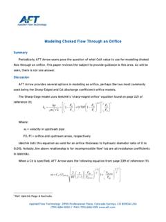
2 Ph: (217)774-5342. Under contract with: Igneus Incorporated Name of designer: Trevor Spain, NICET #113061. Automatic Sprinkler System Layout Level IV. Authority having jurisdiction: None Notes Basic tree system piping layout using the "system helper" commands. Crossmain modified for obstruction. See the "Getting Started" guide for instruction. 10/16/2009 Page 2. Hydraulic Demand Graph 70. Water Source: (A) A) 62 psi Static B) 700 gpm at psi 60. (B) Source at BOR: C) psi Static 50 D) gpm at psi E) 700 gpm at psi (C) (D). 40 (E) Demand at BOR: P F) gpm at psi (F). S. I. 30. 20. 10. 0. 0100 200 300 400 500 600 700. GPM. report created by the "Simple Hydraulic Calculator" from 10/16/2009 Page 3. Supply Analysis Static Residual Available Total Required Node at Pressure Pressure Flow Pressure Demand Pressure [psi] [psi] [gpm] [psi] [gpm] [psi].
3 Src Node Analysis Elev Pressure ReqDisch discharge Elev Pressure ReqDisch discharge Node Tag [ft] Type [psi] [gpm] [gpm] Node Tag [ft] Type [psi] [gpm] [gpm]. Src source L6-6 ref Tap ref L7-1 ref Spg ref L7-2 ref Bor ref L7-3 ref Tor ref L7-4 ref M1-1 ref L7-5 ref M1-2 ref L7-6 ref M1-3 ref L8-1 ref M1-4 ref L8-2 ref M1-5 ref L8-3 ref M1-6 ref L8-4 ref M1-7 ref L8-5 ref M1-8 ref L8-6 ref L1-1 K= R1-1 ref L1-2 K= R1-2 ref L1-3 K= R1-3 ref L1-4 K= R1-4 ref L1-5 K= R1-5 ref L1-6 ref R1-6 ref L2-1 K= R1-7 ref L2-2 K= R1-8 ref L2-3 K= L2-4 K= L2-5 K= L2-6 ref L3-1 K= L3-2 K= L3-3 K= L3-4 K= L3-5 K= L3-6 ref L4-1 K= L4-2 ref L4-3 ref L4-4 ref L4-5 ref L4-6 ref L5-1 ref L5-2 ref L5-3 ref L5-4 ref L5-5 ref L5-6 ref L6-1 ref L6-2 ref L6-3 ref L6-4 ref L6-5 ref report created by the "Simple Hydraulic Calculator" from 10/16/2009 Page 4.
4 pipe Information Node 1 discharge Nom Fittings L [ft] material Pressure pipe Elev & Flow num & length F [ft] C factor Summary Node 2 [ft] K-factor [gpm] [in] [ft] T [ft] psi/ft [psi] Notes Src q= 8 CDI Pt= Pe= City Q= C=140 Pf= Pv= Tap q= Pt= Vel= Tap q= 6 1LE= CDI Pt= Pe= Leadin Q= 1T= C=140 Pf= Pv= Spg q= Pt= Vel= Spg q= 4 S10 Pt= Pe= Pdev= psi Rpz Q= C=120 Pf= Pv= Bor q= Pt= Vel= Bor q= 4 2E= S10 Pt= Pe= Riser Q= C=120 Pf= Pv= Tor q= Pt= Vel= Tor q= 4 S10 Pt= Pe= Bulk Q= C=120 Pf= Pv= M1-8 q= Pt= Vel= M1-1 q= 4 S10 Pt= Pe= M1-1 Q= C=120 Pf= Pv= M1-2 q= Pt= Vel= M1-2 q= 4 4E= S10 Pt= Pe= M1-2 Q= C=120 Pf= Pv= M1-3 q= Pt= Vel= M1-3 q= 4 S10 Pt= Pe= M1-3 Q= C=120 Pf= Pv= M1-4 q= Pt= Vel= M1-4 q= 4 S10 Pt= Pe= M1-4 Q= C=120 Pf= Pv= M1-5 q= Pt= Vel= M1-5 q= 4 S10 Pt= Pe= M1-5 Q= C=120 Pf= Pv= M1-6 q= Pt= Vel= M1-6 q= 4 S10 Pt= Pe= M1-6 Q= C=120 Pf= Pv= M1-7 q= Pt= Vel= M1-7 q= 4 S10 Pt= Pe= M1-7 Q= C=120 Pf= Pv= M1-8 q= Pt= Vel= L1-1 q= 1 S40 Pt= Pe= L1-1 Q= C=120
5 Pf= Pv= L1-2 q= Pt= Vel= L1-2 q= S40 Pt= Pe= L1-2 Q= C=120 Pf= Pv= L1-3 q= Pt= Vel= report created by the "Simple Hydraulic Calculator" from 10/16/2009 Page 5. pipe Information, cont. Node 1 discharge Nom Fittings L [ft] material Pressure pipe Elev & Flow num & length F [ft] C factor Summary Node 2 [ft] K-factor [gpm] [in] [ft] T [ft] psi/ft [psi] Notes L1-3 q= S40 Pt= Pe= L1-3 Q= C=120 Pf= Pv= L1-4 q= Pt= Vel= L1-4 q= S40 Pt= Pe= L1-4 Q= C=120 Pf= Pv= L1-5 q= Pt= Vel= L1-5 q= S40 Pt= Pe= L1-5 Q= C=120 Pf= Pv= L1-6 q= Pt= Vel= L1-6 q= 2 1E= S40 Pt= Pe= L1-6 Q= C=120 Pf= Pv= R1-1 q= Pt= Vel= L2-1 q= 1 S40 Pt= Pe= L2-1 Q= C=120 Pf= Pv= L2-2 q= Pt= Vel= L2-2 q= S40 Pt= Pe= L2-2 Q= C=120 Pf= Pv= L2-3 q= Pt= Vel= L2-3 q= S40 Pt= Pe= L2-3 Q= C=120 Pf= Pv= L2-4 q= Pt= Vel= L2-4 q= S40 Pt= Pe= L2-4 Q= C=120 Pf= Pv= L2-5 q= Pt= Vel= L2-5 q= S40 Pt= Pe= L2-5 Q= C=120 Pf= Pv= L2-6 q= Pt= Vel= L2-6 q= 2 1E= S40 Pt= Pe= L2-6 Q= C=120 Pf= Pv= R1-2 q= Pt= Vel= L3-1 q= 1 S40 Pt= Pe= L3-1 Q= C=120 Pf= Pv= L3-2 q= Pt= Vel= L3-2 q= S40 Pt= Pe= L3-2 Q= C=120 Pf= Pv= L3-3 q= Pt= Vel= L3-3 q= S40 Pt= Pe= L3-3 Q= C=120 Pf= Pv= L3-4 q= Pt= Vel= L3-4
6 Q= S40 Pt= Pe= L3-4 Q= C=120 Pf= Pv= L3-5 q= Pt= Vel= report created by the "Simple Hydraulic Calculator" from 10/16/2009 Page 6. pipe Information, cont. Node 1 discharge Nom Fittings L [ft] material Pressure pipe Elev & Flow num & length F [ft] C factor Summary Node 2 [ft] K-factor [gpm] [in] [ft] T [ft] psi/ft [psi] Notes L3-5 q= S40 Pt= Pe= L3-5 Q= C=120 Pf= Pv= L3-6 q= Pt= Vel= L3-6 q= 2 1E= S40 Pt= Pe= L3-6 Q= C=120 Pf= Pv= R1-3 q= Pt= Vel= L4-1 q= 1 S40 Pt= Pe= L4-1 Q= C=120 Pf= Pv= L4-2 q= Pt= Vel= L4-2 q= S40 Pt= Pe= L4-2 Q= C=120 Pf= Pv= L4-3 q= Pt= Vel= L4-3 q= S40 Pt= Pe= L4-3 Q= C=120 Pf= Pv= L4-4 q= Pt= Vel= L4-4 q= S40 Pt= Pe= L4-4 Q= C=120 Pf= Pv= L4-5 q= Pt= Vel= L4-5 q= S40 Pt= Pe= L4-5 Q= C=120 Pf= Pv= L4-6 q= Pt= Vel= L4-6 q= 2 1E= S40 Pt= Pe= L4-6 Q= C=120 Pf= Pv= R1-4 q= Pt= Vel= L5-1 q= 1 S40 Pt= Pe= L5-1 Q= C=120 Pf= Pv= L5-2 q= 0 Pt= Vel= L5-2 q= S40 Pt= Pe= L5-2 Q= C=120 Pf= Pv= L5-3 q= 0 Pt= Vel= L5-3 q= S40 Pt= Pe= L5-3 Q= C=120 Pf= Pv= L5-4 q= 0 Pt= Vel= L5-4 q= S40 Pt= Pe= L5-4 Q= C=120 Pf= Pv= L5-5 q= 0 Pt= Vel= L5-5 q= S40 Pt= Pe= L5-5 Q= C=120 Pf= Pv= L5-6 q= 0 Pt=
7 Vel= L5-6 q= 2 1E= S40 Pt= Pe= L5-6 Q= C=120 Pf= Pv= R1-5 q= 0 Pt= Vel= report created by the "Simple Hydraulic Calculator" from 10/16/2009 Page 7. pipe Information, cont. Node 1 discharge Nom Fittings L [ft] material Pressure pipe Elev & Flow num & length F [ft] C factor Summary Node 2 [ft] K-factor [gpm] [in] [ft] T [ft] psi/ft [psi] Notes L6-1 q= 1 S40 Pt= Pe= L6-1 Q= C=120 Pf= Pv= L6-2 q= 0 Pt= Vel= L6-2 q= S40 Pt= Pe= L6-2 Q= C=120 Pf= Pv= L6-3 q= 0 Pt= Vel= L6-3 q= S40 Pt= Pe= L6-3 Q= C=120 Pf= Pv= L6-4 q= 0 Pt= Vel= L6-4 q= S40 Pt= Pe= L6-4 Q= C=120 Pf= Pv= L6-5 q= 0 Pt= Vel= L6-5 q= S40 Pt= Pe= L6-5 Q= C=120 Pf= Pv= L6-6 q= 0 Pt= Vel= L6-6 q= 2 1E= S40 Pt= Pe= L6-6 Q= C=120 Pf= Pv= R1-6 q= 0 Pt= Vel= L7-1 q= 1 S40 Pt= Pe= L7-1 Q= C=120 Pf= Pv= L7-2 q= 0 Pt= Vel= L7-2 q= S40 Pt= Pe= L7-2 Q= C=120 Pf= Pv= L7-3 q= 0 Pt= Vel= L7-3 q= S40 Pt= Pe= L7-3 Q= C=120 Pf= Pv= L7-4 q= 0 Pt= Vel= L7-4 q= S40 Pt= Pe= L7-4 Q= C=120 Pf= Pv= L7-5 q= 0 Pt= Vel= L7-5 q= S40 Pt= Pe= L7-5 Q= C=120 Pf= Pv= L7-6 q= 0 Pt= Vel= L7-6 q= 2 1E= S40 Pt= Pe= L7-6 Q= C=120 Pf= Pv= R1-7 q= 0 Pt= Vel= L8-1 q= 1 S40 Pt= Pe= L8-1 Q= C=120 Pf=
8 Pv= L8-2 q= 0 Pt= Vel= L8-2 q= S40 Pt= Pe= L8-2 Q= C=120 Pf= Pv= L8-3 q= 0 Pt= Vel= report created by the "Simple Hydraulic Calculator" from 10/16/2009 Page 8. pipe Information, cont. Node 1 discharge Nom Fittings L [ft] material Pressure pipe Elev & Flow num & length F [ft] C factor Summary Node 2 [ft] K-factor [gpm] [in] [ft] T [ft] psi/ft [psi] Notes L8-3 q= S40 Pt= Pe= L8-3 Q= C=120 Pf= Pv= L8-4 q= 0 Pt= Vel= L8-4 q= S40 Pt= Pe= L8-4 Q= C=120 Pf= Pv= L8-5 q= 0 Pt= Vel= L8-5 q= S40 Pt= Pe= L8-5 Q= C=120 Pf= Pv= L8-6 q= 0 Pt= Vel= L8-6 q= 2 1E= S40 Pt= Pe= L8-6 Q= C=120 Pf= Pv= R1-8 q= 0 Pt= Vel= M1-1 q= 2 1T= S40 Pt= Pe= R1-1 Q= C=120 Pf= Pv= R1-1 q= Pt= Vel= M1-2 q= 2 1T= S40 Pt= Pe= R1-2 Q= C=120 Pf= Pv= R1-2 q= Pt= Vel= M1-3 q= 2 1T= S40 Pt= Pe= R1-3 Q= C=120 Pf= Pv= R1-3 q= Pt= Vel= M1-4 q= 2 1T= S40 Pt= Pe= R1-4 Q= C=120 Pf= Pv= R1-4 q= Pt= Vel= M1-5 q= 2 1T= S40 Pt= Pe= R1-5 Q= C=120 Pf= Pv= R1-5 q= 0 Pt= Vel= M1-6 q= 2 1T= S40 Pt= Pe= R1-6 Q= C=120 Pf= Pv= R1-6 q= 0 Pt= Vel= M1-7 q= 2 1T= S40 Pt= Pe= R1-7 Q= C=120 Pf= Pv= R1-7 q= 0 Pt= Vel= M1-8 q= 2 1T= S40 Pt= Pe= R1-8 Q= C=120 Pf= Pv= R1-8 q= 0 Pt= Vel= Material
9 Codes pipe Material Fittings CDI - Cement Lined Ductile Iron Thickness Class 50 E - Standard 90 degree elbow S10 - Schedule 10 Steel T - Tee - Flow turn 90 degrees S40 - Schedule 40 Steel LE - Long Radius 90 degree elbow report created by the "Simple Hydraulic Calculator" from 10/16/2009 Page 9. Flow Diagram ( 1 of 1 ). R1-8. L8-1 L8-2 L8-3 L8-4 L8-5 L8-6 M1-8. R1-7. L7-1 L7-2 L7-3 L7-4 L7-5 L7-6 M1-7. R1-6. L6-1 L6-2 L6-3 L6-4 L6-5 L6-6 M1-6. R1-5. L5-1 L5-2 L5-3 L5-4 L5-5 L5-6 M1-5. * R1-4. L4-1 L4-2 L4-3 L4-4 L4-5 L4-6 M1-4. * * * * * R1-3. L3-1 L3-2 L3-3 L3-4 L3-5 L3-6 M1-3. * * * * * R1-2. L2-1 L2-2 L2-3 L2-4 L2-5 L2-6 M1-2. * * * * * R1-1. L1-1 L1-2 L1-3 L1-4 L1-5 L1-6 M1-1. report created by the "Simple Hydraulic Calculator" from 10/16/2009 Page 10. Backflow Preventer in pipe "Rpz".
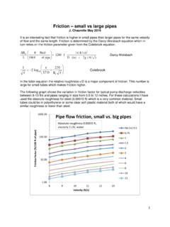
10 (I). 35. Given Values: A) 12 psi at gpm B) 40 gpm at 12 psi 30 C) 110 gpm at 8 psi D) 300 gpm at 8 psi (H) E) 400 gpm at 10 psi 25 F) 500 gpm at 14 psi G) 600 gpm at 17 psi H) 800 gpm at psi 20. P Extrapolated: S (G) I) gpm at 35 psi I. 15 (F) Calculated: (A)(B) X) gpm at psi (E). 10. (C) (D). 5. 0. 0 250 500 750 1000 1250 1500 1750. GPM. report created by the "Simple Hydraulic Calculator" from