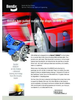
Transcription of 1 2 Air Brake System
1 PP-5 Control Typical Tractor System Schematic Typical Truck System Schematic Valve with bendix Components with bendix Components MV-3 TP-3DC Tractor Hose Couplings Control Control Valve Protection Valve & WS-24 Wheel Speed Sensor 6. Supply PP-DC Park . WS-24 Wheel Control Valve bendix EC-60 . Speed Sensor Stop Light Switch Electronic Controller ADB-22X . ADB-22X Air disc Air disc Standard1. Premium2 Brake Brake ADB-22X . Air disc ADB-22X . TCS-9000 Air disc Brake bendix EC-60. Valve Brake Electronic Controller Standard1 M-32 / M-32QR . M-32 /. M-32QR . Premium2. Air Brake System Modulator (4 places). SR-7 . Spring Brake Modulator Quick Modulating Troubleshooting (4 places) Release Valve Valve Service Quick E-8P / E-6 Brake Valve Relay Valve Release Valve E-8P / E-6 Brake R-12 /R-14.
2 Valve with BVA-85 Service QR-1C Quick PR-3 /. Relay Valve Release Valve PR-4 Low Brake Valve Actuator To Accessories Valve Pressure Indicator AD-9 /. AD-IP . Low Pressure Air Dryer Indicator AD-IS . Air Dryer TRUCKS AND TRUCK TRACTORS: Front Axle Reservoir Safety Valve Front Charging Primary Secondary Park Parking Accessories Supply Rear Axle Reservoir Reservoir Axle Reservoir (Supply) (Control). Tu-Flo 550/Tu-Flo 750/ WS-24 Wheel ES Drum Brake w/ BA-921 / BA-922 Speed Sensor Rear Notes: ES Drum Brake w/. Versajust Automatic Slack WS-24 Wheel Air Compressor Tu-Flo 550/Tu-Flo 750/ Axle Reservoir The color coding of the Brake System schematic follows TMC Recommended Practice #423. Versajust Automatic ES Drum Brake w/.
3 ES Drum Brake w/ Adjuster and SB-4 Spring Speed Sensor BA-921 / BA-922 Air disc & drum Brake actuation combined on a single axle are shown for pictorial purposes only. Slack Adjuster and Versajust Automatic Slack Versajust Automatic Brake Chamber Adjuster and SB-4 Spring Slack Adjuster and Air Compressor 1 Service Chamber Equipped with standard bendix ABS Antilock Brake System Brake Chamber Service Chamber 2. Equipped with bendix ABS and Smart ATC Traction Control To Accessories bendix brand wheel end solutions are brought to you by bendix brand wheel end solutions are brought to you by bendix Spicer Foundation Brake LLC, a bendix CVS and Dana joint venture. bendix Spicer Foundation Brake LLC, a bendix CVS and Dana joint venture.
4 TEST 1 CHECKLIST 2 TEST 4 TEST 5 TEST 6 Continued Governor cut-out / Low pressure warning / Pressure build-up If there is excessive leakage in the supply side of the pneumatic System , one or more Leakage service air delivery Manual Parking Brake Operation Specify genuine bendix replacement parts every time you . VEHICLE PARKED, WHEELS CHOCKED OK Not of the following devices could be causing the problem: FULL PRESSURE, ENGINE STOPPED, PARKING BRAKES RELEASED OK Not FULL PRESSURE, ENGINE IDLING 600-900 RPM OK Not OK Not service your air Brake System . OK NOTE: A leak detector or soap solution will aid in locating the faulty component. OK OK OK. 1. Supply lines and fittings All genuine bendix replacement parts are manufactured to meet 1.
5 Drain all the reservoirs to 0 psi. 1. Make and hold an 80-90 psi Brake application. This can be accomplished by FOR STRAIGHT TRUCKS, BUSES AND BOBTAIL TRACTORS: 3. Pop Pressure Vehicle Test Procedure (Continued). 2. Low pressure indicator(s) using the bendix BVA-85 Brake valve actuator. If the vehicle is not equipped original OE specifications to guarantee quality, reliability and 2. Start the engine and run at fast idle. The low pressure warning should be 1. Manually operate the park control, yellow button valve, and note that parking A. Install an accurate shop standard pressure gauge in the secondary service proper operating performance. 3. Service Brake relay valve(s) with a BVA-85 Brake valve actuator, an assistant should be used to maintain a on.
6 Note: on vehicles equipped with ABS, the warning lamp will also come on brakes apply and release promptly as the control valve button is pulled out and reservoir. 4. Spring Brake relay valve (where applicable) constant application during these tests. Rely on genuine bendix replacement parts to keep your air Brake momentarily when the ignition is turned on. On some systems, such as the pushed in. B. Build pressure in the service reservoirs until the compressor cut-out is bendix AD-IS dryer System (illustrated), reservoirs may not fill simultaneously 5. Dual Brake valve 2. Allow pressure to stabilize for 1 minute; then begin timing for 2 minutes while System operating efficiently. FOR TRACTOR/TRAILER COMBINATIONS: reached, shut the engine off.
7 And one reservoir may fill to 110 psi before the other starts to fill. 6. Trailer hand control valve watching the dash gauges for a pressure drop. 1. Manually operate the tractor protection control valve (trailer supply valve usually With thousands of authorized bendix parts outlets across North 7. Parking control valve C. Fully open the manual drain valve on the primary service reservoir allowing 3. Low pressure warning; dash warning lamp should go off above 60 psi. A. Pressure Drop: Single Vehicle (A 4 psi drop within 2 minutes is allowable for red octagonal button). Note that trailer brakes apply and release promptly as the the reservoir to drain completely. America, you're never far from quality genuine bendix replacement 8.)
8 System safety valve(s) in the supply reservoir and/or air dryer either service reservoir). 4. Build up time; pressure should build from 85-100 psi within 40 seconds. control button is pulled out and pushed in. parts. 9. Governor (may be mounted on the air dryer as illustrated, on the compressor, or remotely) D. Open the secondary reservoir's manual drain valve creating a bleed rate of B. Pressure Drop: Tractor/Trailer (A 6 psi drop within 2 minutes is allowable for 2. Manually operate System park control (usually yellow diamond button) and note 10. Compressor discharge line approximately 20-50 psi/min. 5. Governor cut-out; cuts out at the correct pressure, usually 125-135 psi. either service reservoir) all parking brakes (tractor and trailer) apply promptly.
9 RETEST TO VERIFY PROPER OPERATION OF ALL ITEMS REPAIRED OR REPLACED. E. Monitor the pressure gauge noting the pressure at which the parking control 6. Governor cut-in; reduce the service air pressure to governor cut-in. The C. Pressure Drop: Tractor/2 Trailers (An 8 psi drop within 2 minutes is allowable MAKE ALL NECESSARY REPAIRS BEFORE PROCEEDING TO TEST 6; automatically pops . This is not a Federal requirement - See Note in previous difference between cut-in and cut-out pressure must not exceed 30 psi. for either service reservoir). SEE CHECKLIST 5 FOR COMMON CORRECTIONS. column. TEST 3 3. Check Brake chamber push rod travel (refer to chart below for the CVSA Max Visit or for MAKE ALL THE NECESSARY REPAIRS BEFORE PROCEEDING TO TEST 2; 4.)
10 For Towing Vehicles Only - Test the tractor protection valve feature Pressure Modulator Valve and Traction Control Valve Chuff Test allowable Stroke). With the parking brakes released and service brakes applied Service Data Sheets and other literature such as the following: SEE CHECKLIST 1 FOR COMMON CORRECTIONS. CHECKLIST 5 A. Charge the air System to governor cut-out. FULL PRESSURE, ENGINE STOPPED, PARKING BRAKES RELEASED OK Not with 80 to 90 psi of air pressure to the service chambers. BW2780 Troubleshooting bendix ESP Stability System CHECKLIST 1 OK If sluggish performance is noted in either test, check for: BW1555 Brake Balance Procedure Brake Chamber Type CVSA Max. Allowable Stroke B. Disconnect the service or control (blue) line to the trailer.