Transcription of Lecture 26: Quadrature (90º) Hybrid.
1 Whites, EE 481/581 Lecture 26 Page 1 of 11. Lecture 26: Quadrature (90 ) hybrid . Back in Lecture 23, we began our discussion of dividers and couplers by considering important general properties of three- and four-port networks. This was followed by an analysis of three types of three-port networks in Lectures 24 and 25. We will now move on to (reciprocal) directional couplers, which are four-port networks. As in the text, we will consider these specific types of directional couplers: 1. Quadrature (90 ) hybrid , 2. 180 hybrid , 3. Coupled Line, and 4. Lange Coupler.
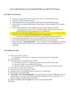
2 We will begin with the Quadrature (90 ) hybrid . Fig shows this coupler implemented with microstrip as a 1:1 power divider: Because of the physical symmetry, we can simplify the analysis of this circuit considerably using even-odd mode analysis. This 2016 Keith W. Whites Whites, EE 481/581 Lecture 26 Page 2 of 11. process is similar to what we did in the last Lecture with the Wilkinson power divider. Even-Odd Mode Analysis of the Quadrature hybrid The normalized (wrt Z 0 ) TL circuit is shown in Fig , minus the return lines: A symmetric (even mode) excitation of this circuit is shown in Fig.
3 : A1e . B1e B2e 1. A4e . B4e B3e 1. /8. and an anti-symmetric (odd mode) excitation is shown in Fig. : Whites, EE 481/581 Lecture 26 Page 3 of 11. A1o . B1o B2o A4o . o o B4 B3. /8. Observe that the circuit and its boundary conditions remain the same in both the even and odd mode configurations. It is only the excitation that changes. Because of this and the circuit being linear, by superposition the total solution is simply the sum of the even and odd mode voltage wave amplitude solutions. Each solution (even and odd) is simpler to determine than the complete circuit, which is why we employ this technique.
4 Even mode. Because the voltages and currents must be the same above and below the line of symmetry (LOS) in Fig , then I 0 at the LOS open circuit loads at the ends of /8 stubs, as shown. Referring to the definition of Bi ( i 1, , 4 ) in Fig , we can write from Fig that for the even mode excitation: B1e e A1e , B2e Te A1e (1a). B3e B2e Te A1e , B4e B1e e A1e (1b). where A1e 1 2 , and e and Te are the reflection and transmission coefficients for the even mode configuration. (We'll solve for these coefficients shortly.). Whites, EE 481/581 Lecture 26 Page 4 of 11.
5 Odd mode. Because the voltages and currents must have opposite values above and below the LOS in Fig , then V 0 along the LOS short circuit loads at the ends of /8. stubs, as shown. Then, B1o o A1o , B2o To A1o (2a). B3o B2o To A1o , B4o B1o o A1o (2b). where A1o 1 2 and o and To are reflection and transmission coefficients for the odd mode configuration. Total solution. The total solution is the sum of the voltages and voltage wave amplitudes in both circuits. From this fact, we can deduce that the total Bi coefficients will be the sum of (1) and (2): 1 1. B1 B1e B1o e o ( ),(3).
6 2 2. 1 1. B2 B2e B2o Te To ( ),(4). 2 2. 1 1. B3 B3e B3o Te To ( ),(5). 2 2. 1 1. B4 B4e B4o e o ( ),(6). 2 2. Likewise, the incident wave coefficients are 1 1. A1 A1e A1o 1. 2 2. 1 1. A4 A4e A4o 0. 2 2. Whites, EE 481/581 Lecture 26 Page 5 of 11. These match the assumed excitation in the original circuit on p. 2. To finish the calculation of the S parameters for the Quadrature hybrid , we need to determine the reflection and transmission coefficients for the even- and odd-mode configurations. These are two-port networks that are much easier to solve than the original four-port Quadrature hybrid .
7 Your text shows that the solutions for e and Te are 1. e 0 and Te 1 j ( ),(7),(8). 2. Here we'll derive solutions for o and To . From Fig : 12 To 1 1 2 1. o 1 1. We have three cascaded elements, so we'll use ABCD. parameters to solve for the overall S parameters of this circuit. Elements 1 and 3. These are short circuit stubs of length 8 , which appear as the shunt impedance 2 . Z in jZ 0 tan l where l . 8 4. Whites, EE 481/581 Lecture 26 Page 6 of 11. Z in Therefore, j , or YN j Z0. From the inside flap of your text: 1 0 1 0 . ABCD j 1 (9). N. Y 1 . Element 2.
8 This is a /4-length of TL where 2 . l . 4 2. From the inside flap of your text: Z0 2 . cos l j sin l j . 0. 2 . Z . ABCD 0.. Z0 . j sin l cos l j 2 0 . Z0 2 . Cascading these three ABCD matrices we find the overall ABCD. matrix for odd mode excitation: j . A B 1 0 0 1 0 1 1 j . C D j 1 2.. j 1 (10). o j 1 2 . j 2 0 . Using Table , we can convert these to S parameters (with Z 0 1 for the normalized TL): A B Z 0 CZ 0 D 1 2 1 j j 1. S11 0 (11). A B Z 0 CZ 0 D 1 2 1 j j 1. Whites, EE 481/581 Lecture 26 Page 7 of 11. 2 2 1. S 21 . A B Z 0 CZ 0 D 1 2 1 j j 1. (12).
9 2 2 2.. 2 2 j 1 j Since the ports are matched, then: o S11 0 ( ),(13). 2 1 j 1. and To S 21 1 j ( ),(14). 1 j 1 j 2. Finally, using (7), (8), (13), and (14) in (3)-(6) we find: B1 0 ( ),(15). 1 1 j B2 1 j 1 j ( ),(16). 2 2 2 2 2. 1 1 1 1. B3 1 j 1 j ( ),(17). 2 2 2 2 2. 1 1. B4 0 0 0 ( ),(18). 2 2. These Bi form the first column of the S matrix for the hybrid Quadrature . When properly interpreted, these results tell us much about the circuit. In particular, when port 1 is excited and all other ports terminated in matched loads, then: B1 0 port 1 is matched. Whites, EE 481/581 Lecture 26 Page 8 of 11.
10 B2 j 2 90 phase shift from port 1 to port 2, and one half of the time average input power is delivered to port 2. B3 1 2 180 phase shift from port 1 to port 3. (90 phase shift between ports 3 and 2), and one half of the input power is delivered to port 3. (Hence, 1:1 power division.). B4 0 no power output to port 4. Because of the high degree of symmetry, we can treat any port as the input port. Then, the isolation is the other port on the same side as the input and the outputs are the two ports on the other side of the circuit. Employing this concept and the results above, we can construct the other three columns in the full S matrix for the Quadrature (90 ) hybrid by simply transposing rows of the first column: 0 j 1 0.