Transcription of Group Delay - Explanations and Applications
1 Group Delay - Explanations and Applications Applied Group Delay Radio Explanations and Applications Labs Design File: DN004 15 November 1999. that the Group Delay is in some way related to signal Introduction Delay . The Group Delay may also be referred to as envelope Delay . Group Delay is a concept that radio engineers are encountering more frequently as higher performance digital communication systems are developed. It The Delay of Signals appears that frequency selective components have Given a filter and a plot of Group Delay , it is natural to Group Delay which, in most cases, seems to degrade assume that this is in some way enables one to system performance. This article addresses several determine the Delay of signals through the filter. The aspects of this topic: answer is that Group Delay and signal Delay are related, but not always in an obvious manner.
2 1. Must we have Group Delay ? 2. The relationship between Group Delay and signal To start, consider how do we measure Delay ? The Delay . obvious way is to put a pulse into the filter and see how 3. Negative Group Delay long we have to wait until it comes out. Consider a 4. The relationship between Group Delay and filter simple low pass filter: loss in passive filters R. Definition of Group Delay Vi C. Vo Group Delay has a mathematical definition (unfortunately), and so we should start with that. Figure 2 - RC Low Pass Filter Given a linear system block with frequency domain The transfer function is transfer function H ( j ). 1. H ( j ) = (3). H(j ) 1 + j / 0. o . ( ) = = (4). Figure 1 - Linear Component + o 1 + 2 2. 2 2. Writing 1 1. j ( j ). with o = =. H ( j ) = A( j )e (1) RC . The Group Delay at = 0 is and it gets less at then the Group Delay is defined as higher frequencies.
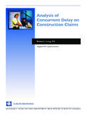
3 The Group Delay is plotted in the following figure for = 1 . ( ). ( ) = (2). 1. That is, it is the negative of the rate of change of phase with frequency. The quantity has the dimension of Group Delay time, but the question is; what time does it represent? Many textbooks follow the definition of Group Delay with a discussion of an ideal element that delays a signal by time T (for example an ideal lossless transmission line). This Delay element has a transfer function of 0. 0 1 2 3 4 5. H ( j ) = e j T (3) Frequency Figure 3 - Group Delay of RC Filter and it is can be seen that the Group Delay is T for all frequencies. By analogy with this then it is implied Applied Radio Labs 1999 Page 1 of 6. Group Delay - Explanations and Applications The rising edge of the input pulse is represented as a RF Signals and Envelope Delay step function at t=0, and the output waveform is calculated to be RF engineers are more typically concerned with bandpass systems.
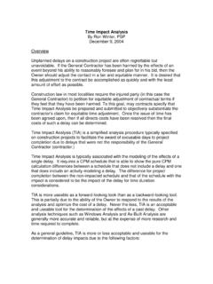
4 A typical filter may be used for transmitting one or a number of signals. v o ( t ) = 1 e t / = 1 e o t (5). For example consider a radio system operating in a which is plotted in the following figure, again for the channel at 850 MHz (such as IS95). If this case of = 1 signal is passed through a 25 MHz bandpass filter in a base station, then it is meaningful to ask what Delay the signal experiences. The analogy to the pulse response in the low pass case is the response of the 1 bandpass filter to a burst of carrier. The start of the carrier burst is shown below: Vo(t). 1. Voltage 0. 0 1 2 3 4 5 6 0. Time (sec). Figure 4 - Step Response of RC Filter -1. If we define the pulse Delay as the Delay to the 50% -1 0 1 2 3 4 5. point, this occurs at t = . Can we predict this Time easily from the Group Delay graph?
5 Not easily. The Figure 5 - Start of Carrier Burst signal value at time equal to the DC Group Delay is Maybe we should measure all delays at the When passed through the filter, the output may be point? something like As in this example, filters often change the shape of signals (this may in fact be the reason it is being used). In general, if the filter significantly changes the shape 1. of the signal, then the Delay measurement is somewhat arbitrary and not easily related to the Group Delay . Voltage This does not mean that it is not useful to have specific 0. definitions of Delay for particular Applications . For example it may be useful to define the Delay of a logic filter to be that to the 50% point, as that is the threshold level of a particular logic gate. All we are -1. saying is that this Delay is not directly related to the Group Delay of the filter.
6 Typically a filter used for -1 0 1 2 3 4 5. pulse shaping has specifications on risetime and pulse Time Delay (with specific definition), and these Figure 6 - Filtered RF Burst requirements are usually analysed by analysing or simulating the filter in the time domain, not by considering the Group Delay . The rising edge of the envelope has been delayed, in a similar fashion to the low pass filter. If we analysed There are more mathematical treatments of pulse this in detail, we would find that the Delay depended transmission, Kuo [2] provides some references. on the point on the envelop chosen for measurement, and would generally be difficult to relate to the Group Thus, Group Delay is not directly applicable to Delay characteristics of the filter. The analogy of the determining the pulse Delay of a low pass filter, unless low pass case is that if the envelope undergoes the pulse shape is passed reasonably undistorted by the significant change of shape, then the Delay is not easily filter.
7 The reason for this will become clearer in the related to the Group Delay . next section. Applied Radio Labs 1999 Page 2 of 6. Group Delay - Explanations and Applications When Group Delay equals Must Filters Have Delay Envelope Delay With the exception of the few Applications requiring an Consider a signal that is bandlimited ( essentially all approximation of a time Delay , most engineers would the power lies within some frequency channel). This agree that Group Delay has few redeeming features and signal can be considered a sum of frequency it would be nice if we could discover a set of filters that components across this channel. The filter acts on did not exhibit any of this undesirable characteristic. each component separately. If, over this channel, the Is this possible? filter has a constant amplitude response and a constant Group Delay , then the filter can be replaced by a Delay Clearly we cannot have a filter output appearing before element (and attenuator and a phase shifter).
8 Its input, (this would violate causality) so the signal must have a positive (or zero) Delay , but why does it To summarise, if the filter transfer function is given have to be large enough to concern system designers? by (1) and (2) then A filter has to respond differently to different frequencies. What are the difficulties of the job? Try if it out pretend that you are a low-pass filter with the requirement to pass signals below 1000Hz and stop 1. the amplitude response of the filter is those above 1200Hz. Suppose that you are presented approximately constant A( j o ) over the with a signal containing the following sinusoidal bandwidth of the signal components (because you are new to the job I'll split the signal into the sinusoids for you if you want to do the job on a full-time basis you'll have to learn how to and do that yourself!)
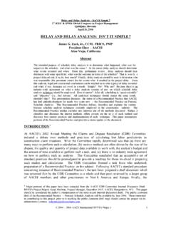
9 2. the Group Delay of the filter is approximately constant ( j o ) over the bandwidth of the a signal then b 3. the output of the filter approximates a replica of the input signal, but time delayed by c ( j o ) , scaled in amplitude by A( j o ) and with a phase shift ( j o ) . 0 1 2. Time(ms). A proof of this is given in the appendix. This is why communications channels have Figure 7 - Input Signals to Filter requirements on both the amplitude response and the Signal a' is at 500Hz, signal b' at 900Hz and signal Group Delay variation. The amplitude response is c' at 1300Hz. often easily associated with the requirement to pass all the signal power. The Group Delay requirement is to Look at signal a'. We are only interested in seeing if minimise Group Delay distortion. The total Delay is signals are below 1kHz to pass, so by 1ms we can be often unimportant (in radio systems it is normally sure that this is a low-frequency signal we'll pass it.)
10 Swamped by the propagation Delay ), however variations in Group Delay across the channel will cause Signal b' is another matter, by 1ms we have almost distortion of the signal waveform. seen a cycle and we are not 100% that it is below 1kHz, just keep it a bit longer to check, by 2ms we are The reliable determination of Group Delay requirements pretty confident that it is below 1kHz so we can let it for any particular communications system must come out. It is now delayed by from some analysis or simulation or measurement of the system when subjected to Group Delay variation. Signal c' is similar to b', except that after we keep it These days, simulations are frequently the simplest for around 2ms we decide not to let it out. way of determining the sensitivity to Group Delay variations.