Transcription of 0-10V Class 1 and Class 2 Wiring - Electrical Sector – Eaton
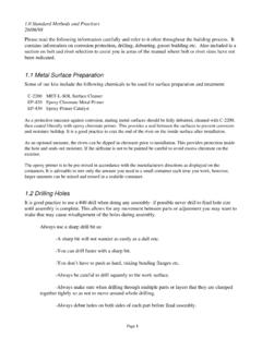
1 Application Note 0-10V Class 1 and Class 2 Wiring Overview 0-10V ballasts and drivers are connected together by a 2-wire low voltage bus that is suitable for Class 1 or Class 2 Wiring installations. This application note explains how both Class 1 and 2 Wiring are made and how they both meet National Electric Code (NEC) regulations. To reduce the risk of interference it's highly recommended that 0-10V and communication wires be run as Class 2. The dimming performance of 0-10V can be impaired if the system is wired in a Class 1. configuration, especially if long distances of line voltage Wiring are used. If Class 1 is desired, then actions should be taken to reduce the length of the 0-10V wires. Wiring Details Class 2 (Preferred Method): The ballasts and drivers seen below are wired in a Class 2 configuration. Positive Conduit LED. LED ARRAY. DRIVER. Negative Positive Conduit LED. LED ARRAY. DRIVER. Negative Figure 1. 0-10V Ballasts and Drivers Wired for Class 2.
2 NNote: For more information on Class 2 Wiring and additional Class 2 Wiring requirements see National Electric Code Article 725. OO With regards to factory installed Wiring , as per UL 1598 section : Factory-installed power limited Wiring and branch circuit Wiring that come in random contact within the luminaire shall have insulation rated for the maximum voltage that exists in any of the circuits. Wiring Details Class 1: Proof 0-10V Class 1 and Class 2 Wiring 0-10V Class 1 and Class 2 Wiring If Wiring with the properly rated insulation is used, then no spacing or separation is required regardless of the circuit conductor voltage. OO Class 2 Wiring of the 0-10V ballasts and drivers follow the NEC Requirement (D) (references to Class 3 are eliminated). Class 2 circuit conductors in compartments, enclosures, device boxes, outlet boxes, or similar fittings shall be permitted to be installed with electric light, power, Class1, circuits where they are introduced solely to connect the equipment connected to Class 2 circuits and where (1) or (2) applies: (1) The electric light, power, Class 1 circuit conductors are routed to maintain a minimum of 6 mm (.)
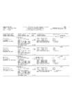
3 25 in) separation from the conductors and cables of Class 2. (2) The circuit conductors operate at 150 volts or less to ground and also comply with one of the following: a. The Class 2 circuits are installed using Type CL3, CL3R, or CL3P or permitted substitute cables provided these Class 3 cable conductors extending beyond the jacket are separated by a minimum of 6 mm ( in). or by a nonconductive sleeve or nonconductive barrier from all other conductors. b. The Class 2 circuit conductors are installed as a Class 1 circuit OO 0-10V ballasts and drivers have a minimum spacing of inches between line voltage and the bus terminals (purple and grey wires) for Class 2 installations. Wiring Details Class 1: The ballasts and drivers seen below are wired in a Class 1 configuration. Positive LED. LED ARRAY. DRIVER. Negative Conduit Junction Box Conduit Positive LED. LED ARRAY. DRIVER. Negative Figure 2. 0-10V Ballasts and Drivers Wired for Class 1. 2 OO Class 1 Wiring methods follow the NEC Requirement Class 1 circuits shall be permitted to be installed with other circuits as specified in (A) and (B): (A) Class 1 circuits shall be permitted to occupy the same cable, cable tray, enclosure, or raceway without regard to whether the individual circuits are alternating or direct current, provided all conductors are insulated for the maximum voltage of any conductors in the cable, cable tray, enclosure or raceway.
4 (B) Class 1 circuits shall be permitted to be installed with power supply conductors as specified: (1) Class 1 and power supply circuits shall be permitted to occupy the same cable, enclosure, or raceway only when functionally associated. OO Since the 0-10V ballast and driver meets Class 2 installation requirements, it can also be installed in a Class 1. configuration when Class 2 markings are not present. The NEC allows the reclassification of Class 2 circuits per Article Exception : Class 2 and circuits shall be permitted to be reclassified and installed as Class 1 circuits if the Class 2 markings .. are eliminated and the entire circuit is installed using the Wiring methods and materials in accordance with Part II, Class 1. circuits. NNote: For more information regarding Class 2 Wiring and additional requirements see the National Electrical Code Article 725. OO The 0-10V ballast and driver is labeled Class 2 rather than Class 1 or Class 2 because the ballast is a sink of power, not a source.
5 According to UL 935 : When the ballast is the sink of a Class 2 limited power circuit shall be identified as such with words Class 2 Circuit . to indicate that the ballast is intended for connection to a Class 2 circuit and that the controlling circuit is not affected by the presence of the ballast. Since the ballast is not a source for this link, it is prohibited from being marked Class 1 or Class 2 even though it is allowed to be wired either way. Reference Information OO Code quotation, guidance, and Wiring guides above are listed for reference only. Always follow local and national Wiring requirements. OO NEC 2008 was used as a reference in this Application Note. More recent releases of the National Electrical Code should always be consulted. OO The National Electrical Code (NEC) is a registered trademark of the National Fire Protection Association, Quincy, MA. Eaton 1000 Eaton Boulevard Cleveland, OH 44122. United States Eaton Lighting Systems Controls Products 203 Cooper Circle Peachtree City, GA.
6 2015 Eaton All Rights Reserved Eaton is a registered trademark. Printed in USA. Publication No. AP503004EN All trademarks are property June 5, 2015 of their respective owners.