Transcription of 0”) - KPM-US
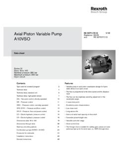
1 axial piston pumps for Open Circuits in Mobile, Industrial and Marine Applications0 )19654Q_F:19654Q_F 12/6/10 10:12 AM Page Description .. Coding .. Description of ..10K3VL60 ..11K3VL80 ..12K3VL112 ..13K3VL140 ..14K3VL200 .. Fluid Start-up ..1710. Drive Shaft Coupling ..20K3VL80 ..22K3VL112/140 ..24K3VL200 ..2712. Response Time ..2813. Through Pump Integral Unloading Valve, Proportional Unloading Valve, Electronic Displacement Control ..3316. Proportional Amplifier .. General DescriptionK3VL series swash-plate type axial piston pumps are designed to satisfy medium to heavy-duty open circuit applica-tions in the mobile, industrial, marine and other industries. The pump s rotating groups are based upon the provendesign of the K3V and K3VG pumps . K3VL pumps are available in nominal displacements ranging from in /rev (28 to 200 cc/rev) with various pressure, flow, and combination control features of K3VL pumps include:- Continuous pressure rating of 4600 psi (320 bar), 3625 psi (250 bar) for High overall efficiency (> 90% peak)- Exceptional self priming American (SAE) or European (ISO) mountingand shaft- Excellent reliability and very long service power to weight control of optional through control Low pulsation and noise Integral unloading valve or proportional pressure relief valve available19654Q_F:19654Q_F 11/29/10 9:22 AM Page SpecificationsTable Input Shaft Torque RatingShaft TypeSAE BSAE BBSAE CSAE CCSAE D/ESAE FInput torque lbf-ft (Nm)126 (171)182 (248)378 (514)610 (827)1014 (1379)1327 (1800)Shaft surface will have finite life due to wear unless adequate lubrication is provided.
2 (45) (60) (80) (112) (140) (200)Rated3625 (250)5075 (350)*1 Peak4060 (280)5800 (400)*2 Self Prime3000270024002400220022001900*3 ( ).78 (3)442055 (25)55 (25)77 (35)220 (100)Mounting 2-BoltSAE C4-BoltSAE EShaftSAE BSpline or KeySAE CSpline or KeySAE DSpline or KeyMounting ShaftSAE FSplineSAE A45 (61)SAE B 115 (155)SAE B-BSAE C295 (400)730 (990)SAE C-C730 (990)SAE D1032 (1400)SAE E *6 1032 (1400)*1 The instant allowable surge pressure as defined by DIN24312. Life and durability of the pump will be affected.*2 Steady state inlet pressure should be greater than or equal to 0 psi (0 bar) gauge.*3 Steady state inlet pressure should be greater than or equal to psi ( bar) gauge. However the maximum charge pressure should not exceed 145 psi (10 bar).*4 At viscosities from 930 to 4650 SUS (200 to 1000 cSt), warm up at no load is required.*5 ISO mounting and shaft also available. Contact Kawasaki for further information.
3 *6 SAE E through drive uses the SAE D shaft 4600 (320)5075 (350) ( ) ( )90 (123)4-BoltSAE D516 (700)516 (700)516 (700)60 (4)-4o to 203o (-20o to 95o)143 (65)2-BoltSAE B214 (290)214 (290)406 (550)251 (340)55 to 4650 (10 to 1000)20/18/15 ISO/DIS 4406 (Class 9)Refer to to Table Drive Torque Rating - lbf-ft (Nm)4600 (320)5075 (350)SAE B-BSpline or KeySAE BSplineSAE C or C-CSpline or Key2-BoltSAE CSAE DSpline or Key15 (1)Input Shaft Torque Rating*4 Viscosity Range - SUS (cSt)Pump Case Prefill Capacity - Gallons (Liters)Weight - lb (kg)*5 Standard Mounting Flange and ShaftOptional Mounting Flangeand ShaftMaximum Contamination LevelTemperature Range - oF (oC)Pump ModelDisplacement - in3/rev (cc/rev)Pressure Rating - psi (bar)Speed Rating(rpm at Max. Displacement)Minimum Operating Speed - rpmMaximum Allowable Case Drain Pressure - psi (bar)19654Q_F:19654Q_F 12/6/10 10:13 AM Page Coding [1] [2]Maximum Displacement2828 cc/rev( in /rev)4545 cc/rev( in /rev)6060 cc/rev( in /rev)8080 cc/rev( in /rev)112112 cc/rev ( in /rev)140140 cc/rev ( in /rev)200200 cc/rev ( in /rev) [3]Design SeriesBSeries B (45-200) CSeries C (K3VL28) [4]Hydraulic Fluid-Mineral oil (Nitrile seals except Viton shaft seal)VViton sealsWWater Glycol [5]Circuit Type1 Open circuit [6]Through Drive0 Without through drive (Right hand rotation only)ASAE A shaft coupling and mountBSAE B shaft coupling and mount*1 BBSAE BB shaft coupling and SAE B mountCSAE C shaft coupling and mountC4 SAE C shaft coupling and SAE C 4 bolt mount*2 CCSAE CC shaft coupling and SAE C mount*2CC4 SAE CC shaft coupling and SAE C 4 bolt mountDSAE D shaft coupling and mountESAE D shaft coupling and SAE E mountRRear ports (No through drive)NWith through drive covered and sealed; no shaft coupling includedSStock model.
4 No steel cover or shaft coupling included [7]Direction of RotationRClockwiseLCounterclockwise (Not available as 0 through drive option)[8] Mounting and KSAE mounting flange with SAE straight key shaftShaft TypeSSAE mounting flange with SAE spline shaftMISO mounting flange with ISO straight key shaftTSAE B mounting flange with SAE B spline shaft (K3VL45 and 60 only)CSAE C mounting flange with SAE C spline shaft (K3VL112 and 140 only)XSAE C mounting flange with SAE C straight key shaft (K3VL112 and 140 only)WSAE C mounting flange with SAE C -C spline shaft (K3VL112 and 140 only)YSAE C mounting flange with SAE C-C straight key shaft (K3VL112 and 140 only)FSAE E mounting flange with SAE F spline shaft (K3VL200 only)[9] Port OptionsSSAE 4-bolt flange ports with UNC threadsMSAE 4-bolt flange ports with metric threads[10] Control DeviceL0 Load sense and pressure cut-offL1 Load sense and pressure cut-off (No bleed off for load sense line)*1 LMLoad sense regulator with integral unloading valve (Normally open)*1 LNLoad sense regulator with integral unloading valve (Normally closed)*1,*3 LVLoad sense regulator with integral proportional relief valve (Industrial applications)*1, *4LV2 Load sense regulator with integral proportional relief valve (mobile applications)P0 Pressure cut-off*1 PMPressure cut-off with integral unloading valve (Normally open)*1 PNPressure cut-off with integral unloading valve (Normally closed)*1,*3 PVPressure cut-off with integral proportional relief valve (Industrial applications)*1, *4PV2 Pressure cut-off with integral proportional relief valve (Mobile applications)
5 [11] Regulator Modifications*1 BlankNo modifications, standard setting differential pressure springsB Regulator bypass block, standard setting differential pressure springs CHigh setting differential pressure springsDRegulator bypass block, high setting differential pressure springs K3VL Series Variable Displacement, axial piston , Open Loop Pump19654Q_F:19654Q_F 11/29/10 9:22 AM Page 53 SSpring type: Ultra-low spring forceLSpring type: Low spring forceMSpring type: Medium spring forceHSpring type: High spring force1-6 Adjustment setting Input Speed = 1150 RPM Motor power K3VL Pump Frame Size HP ft-lbs 45 60 80 112 140 200 5 23 S4 6 27 S3 30 S2 33 S1 S4 S4 8 36 L4 S3 S3 9 39 L3 S2 S2 10 45 L2 S1 S1 S6 11 51 L1 L4 L6 S5 13 60 M4 L3 L5 S4 15 69 M3 L2 L4 S3 S4 16 75 M2 L1 L3 S2 S3 18 81 M1 M4 L2 S1 S2 20 90 H4 M3 L1 L4 S1 24 108
6 H3 M2 M4 L3 L6 25 114 H2 M1 M3 L2 L5 26 120 H1 H3 M2 L1 L4 S2 29 132 H2 M1 M4 L3 S1 33 150 H1 H4 M3 L2 L5 35 162 H3 M2 L1 L4 39 180 H2 M1 M3 L3 49 222 H1 H4 M2 L2 49 225 H3 M1 L1 59 270 H2 H4 M3 66 300 H1 H3 M2 73 333 H2 M1 79 360 H1 H6 87 399 H5 99 450 H4 100 456 H3 115 525 H2 122 555 H1 Input Speed = 1750 RPM Motor power K3VL Pump Frame Size HP ft-lbs 45 60 80 112 140 200 23 S4 9 27 S3 10 30 S2 11 33 S1 S4 S4 12 36 L4 S3 S3 13 39 L3 S2 S2 15 45 L2 S1 S1 S6 17 51 L1 L4 L6 S5 20 60 M4 L3 L5 S4 23 69 M3 L2 L4 S3 S4 25 75 M2 L1 L3 S2 S3 27 81 M1 M4 L2 S1 S2 30 90 H4 M3 L1 L4 S1 36 108 H3 M2 M4 L3 L6 38 114 H2 M1 M3 L2 L5 40 120 H1 H3 M2 L1 L4 S2 44 132 H2 M1 M4 L3 S1 50 150 H1 H4 M3 L2 L5 54 162 H3 M2 L1 L4 60 180 H2 M1 M3 L3 74 222 H1 H4 M2 L2 75 225 H3 M1 L1 90 270
7 H2 H4 M3 100 300 H1 H3 M2 111 333 H2 M1 120 360 H1 H6 133 399 H5 150 450 H4 152 456 H3 175 525 H2 185 555 H1 The shaded areas of the chart indicate torque limiter settingswhich may not allow the pump to achive full flow or Kawasaki for application assistance.
8 [12] Solenoid voltage for115A115 VAC 50/60 Hzintegral unloading valve230A230 VAC 50/60Hz(LN/PN option)6D6 VDC12D12 VDC24D24 VDC[13] Solenoid connector ATwo pin Deutsch DT04-2P connectortypeBDIN Connector - ISO/DIN 43650 - Form A[14] Torque LimitingblankWithout torque limiting or displacement controland Displacement/1 With torque limiting or displacement controlControl[15]**For torque limiting refer to horsepower setting codes belowE0 Electronic displacement controlQOPilot operated displacement control*1 Not available on K3VL28*2 Only available on K3VL112 and K3VL140*3LV and PV options require an amplifier; See section 16 for amplifiers*4LV2/PV2 avaliable with 12 VDC or 24 VDC solenoid coils; See section 16 for amplifiers19654Q_F:19654Q_F 11/29/10 9:22 AM Page Description of RegulatorsRegulator codeHydraulic CircuitR1R4 ATairDrBPLD ifferential Pressure SpoolCut-Off Pressure SpoolPump FlowDelivery PressureWarning: A safety relief valve should be installed in the hydraulic circuit at the pump Load Sense and Pressure Cut-offDescription: The load sense regulator controls the pump displacement to best matchthe flow and pressure requirements of the pump delivery pressure (Dp) is the sum of the load pressure (Ls), and thedifferential pressure ( P) setting.
9 Ls + P = DpWhen the pump discharge pressure reaches the preset value of the cut-off spool, thepump destrokes to limit the outlet pressure to that setting. When the system requiresno flow or pressure, the pump returns to an energy saving low pressure Pressure:Standard Settng - 218 psi (15 bar)Standard Differential PressureAdjustment RangeK3VL45-200:145 psi (10 bar) ~ 300 psi (21 bar)High Differential PressureAdjustment RangeK3VL45-80: 145 psi (10 bar) ~ 652 psi (45 bar)K3VL80-200: 145 psi (10 bar) ~ 870 psi (60 bar)Cut-off Pressure:Standard Setting - 4600 psi (320 bar)Adjustment range - 300 psi (21bar) ~ 4600 psi (320 bar)L1 Option:With the L1 option, the bleed-off orifice (R4) is plugged. When this optionis applied, threre must be another bleed-off orifice in the external valving to preventtrapped Block Option:The bypass block is a manifold which contains a check valveand is sandwiched under load sense regulator.
10 The bypass block allows the tworegulator spools to operate in parallel, enabling faster off stroke times. The perform-ance improvement varies according to operating pressure and pump or LM Loadsense and Pressure Cut-off withIntegrated Unloading Valve*Description:An integrated unloading valve is sandwiched between theload sense regulator and the pump which allows the pump to operatein a low pressure standby Pressure:The standby pressure is approximately200 psi (14 bar) at the minimum differential pressure setting.* Can also be used with the torque limiting and proportionaldisplacement control regulatorsPump FlowDelivery Pressure19654Q_F:19654Q_F 11/29/10 9:22 AM Page 75 Pump FlowDelivery PressureWarning: A safety relief valve should be installed in the hydraulic circuit at the pump codeHydraulic CircuitProportionalRelief ValveR1R3 ATairDrBPLD ifferentialPressure SpoolCut-OffPressure SpoolLV or LV2 Load Sense and Pressure Cut-off withIntegrated Proportional Relief Valve*Description:An integrated proportional relief valve issandwiched between the load sense regulator and pumpto control the maximum operating pressure byvarying an electrical signal to the LV control is designed for industrial applicationsoperating on 24vdc control LV2 control is designed for mobile applicationsoperating on 12vdc or 24vdc control Pressure:The standby pressure isa