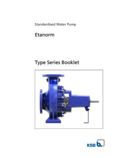
Transcription of 01 2730.5 6-10 E01-09
1 Type series booklet G2 CPKN. Standardized Chemical Pumps to EN 22858/ISO 2858/ISO 5199. Automation products available: PumpExpert PumpDrive (MM). Hyamaster hyatronic Fields of Application Designation For handling aggressive organic and inorganic fluids in the CPKN- C F 40 - 200. chemical and petrochemical industries. They are also used in: Type series refinery off-sites, the paper and cellulose industries, the Material of wetted parts foodstuffs industry, the sugar industry, sea water desalination Additional code plants, absorption equipment in environmental engineering, Discharge nozzle DN. Nominal impeller diameter in mm power stations, etc. Additional codes: H = Heated model O = Open impeller Design F = Off--standard flange design K = Intensively cooled shaft seal chamber Horizontal, radially split volute casing pump in back pull-out X = Special design design, with radial impeller, single-entry, single-stage, to EN 22 858/ISO 2858/ISO 5199.
2 Complemented by pumps of DN 25, DN 200 and above. Operating Data Capacity Q up to 4150 m3/h (1150 l/s). Heads H up to 185 m Pump sizes DN 25 to 400. Operating pressures p up to 25 bar Operating temperatures t -40 to +400 C. Operating temperatures t -40 to +400 C. Certification Certified quality management ISO 9001. CPKN. Selection Charts n = 2900 rpm 3). 3) 3). 3) 3) 3). 3) 3). 3) 3) 3) 3). 3). 3). 3) 3). 3). 3). n = 1450 rpm 1) 1). 1). 1). 3). 3). 3) 3). 3) 2). 3) 3). 3) 3) 3). 3) 3) 3) 3) 3). 3). 3). 3). 3) 3) 3). 3). 3) 3) 3). 3). 3). 1) on request 2) n = 960 rpm 3) heated model --CH possible 2. CPKN. Pressure and Temperature Limits b) Hot water applications a) Where no special regulations apply (technical codes) This applies to pumps not installed in hot water generation plants, pumps which are not subject to the regulations These pumps can be used for all fluids, except for hot water valid for such applications.
3 And organic heat transfer fluids. Permissible pump discharge pressure in bar S2 pump sizes 32-125. Material variants S1 and S2 to 125-400. S2 pump size 150-250 and above Permissible pump discharge pressure in bar S2 pump sizes 32-125. to 125-400 S1. S2 pump size 150-250 and above Temperature of fluid handled in C. Temperature of fluid handled in C. c) Where special regulations apply In case of special regulations, different safety factors are Material variants C1, C3 and E required, which usually leads to a reduction of the limits stated in a). Information about the revision of the application limits has Permissible pump discharge pressure in bar to be requested for each individual case, stating the acceptance specifications. d) Heated model, CPKN-CH. Design g Heated by Hot water/ Thermal oil saturated steam tmax pmax tmax pmax Lantern (344) JL1040 1). O-ring ( )- 183 C 10 bar ---- ---- material EPR.
4 Lantern (344) JS1025 2). Temperature of fluid handled in C O-ring ( )- 250 C 20 bar4) 300 C 6 bar material PTFE/alloyed steel Welded casing cover 300 C 20 bar4) 300 C 6 bar 1) except for pump sizes 250-315, 80-400 and 200-400: pmax = 12 bar, for higher pressures please contact KSB. e) Pressure and temperature limits for shaft seals The application limits of shaft seals depend on the circumferential speed, the material and the fluid handled. They have to be checked in each individual case on the basis of the manufacturer's documentation, taking into account the actual operating conditions. Materials 1). Part description Material variant - standard programme C1 2) / CHs2) S1/S2 E Volute casing JS1025 3) GP240GH+N Noridur Casing cover GP240GH+N / JS1025 4) GP240GH+N 4) Noridur Support foot S235 JRG2 5) S235 JRG2 5) S235 JRG2 5) S235 JRG2 5). Shaft C 45+N 6) C 45+N 6) C 45+N 6) C 45+N 6). Impeller JL1040 7)8) JL1040 7)8) Noridur Bearing bracket JL1040 8) JL1040 8) JL1040 8) JL1040 8).
5 Bearing bracket lantern JL1040 8)9) JL1040 8)9) JL1040 8)9) JL1040 8)9). Seal cover Casing wear ring - JL1040 8) - - Shaft protecting sleeve - gland packing Shaft protecting sleeve - mechanical seal 10) Impeller nut 1) Special materials available, depending on the fluid handled 7) on bearing bracket UP04: JS1025. 2) in compliance with VDMA 24276 at T >350 C or circumferential speed >48 m/sec: 3) EN 1563: GJS-400-18-LT 8) EN 1561: GJL-250. 4) for pump design with conical seal chamber: P250GH 9) for hot water >183 C, for organic heat transfer fluid >200 C, for all T>350. 5) from bearing bracket UP05 JS1030 C and if special regulations apply: JS1025 (EN 1563: GJS-400-18-LT). 6) for wet shaft or T < -10 C : 10) not fitted on wet shaft T < -40 C: T > 250 C: 3. CPKN. Benefits at a Glance Reliable Easy to replace Universal Reduced shaft Reliable operation thanks to thanks to standardized design installation chamber for deflection due to sturdy bearing well--proven and flange variants standardized and due to reinforced assembly and oil hydraulic system cartridge--type mechanical shaft with or without lubrication.
6 Seals shaft protecting Bearing life of more than sleeve 25,000 operating hours Long service life Small stock of spare parts Wide variety of Safety Easy maintenance of bearings and due to the modular design applications thanks to impeller due to constant--level mechanical seals due system due to a wide range of attachment with oiler: constant lubrication, to low radial forces pump materials and metal--to--metal contact easy to check many variants, cooled discharge cover D00458. Conical seal chamber (A-type cover) Model with open impeller (CPKNO) Heatable model (CPKN-CHs). 4. CPKN. Technical Data Pumps on bearing brackets UP02 up to UP04. Pump sizes 100-200. 100-250. 100-315. 100-400. 125-250. 125-315. 125-400. 150-250. 25-160. 25-200. 32-125. 32-160. 32-200. 40-160. 40-200. 50-160. 50-200. 32-250. 40-250. 40-315. 50-250. 50-315. 65-160. 65-200. 65-250. 80-160. 80-200. 80-250. 65-315. 80-315.
7 80-400. Units Bearing bracket UP02 UP03 UP04. General corrosion allowance mm 3 3 3. Impeller outlet width mm 6 6 8 7 7 9 7 15 12 6 7 8 10 8 20 16 13 27 22 17 29 10 14 11 23 19,5 15 32 26 20 46. impeller inlet diameter mm 45 45 52 52 52 65 65 82 82 52 65 65 84 84 89 96 96 100 114 114 122 96 129 118 129 135 129 154 154 154 180. max. impeller diameter mm See individual curve min. impeller diameter mm See individual curve Shaft in stuffing box housing mm 28 / 33 1) 38 / 43 1) 48 / 53 1). diam. pump end mm 35 55 55. at bearings motor end mm 35 55 55. at coupling mm 24 32 42. Shaft Packing mm 35 45 55. prot. sleeve Mechanical seal mm KU 33 / KB 33 KU 43 / KB 43 KU 53 / KB 53. (Standard). Bea- pump end No. NU 307 NU 311 NU 311. rings motor end No. 2 x 7307 BUA 2 x 7311 BUA 2 x 7311 BUA. Shaft deflection At mm at the shaft seal, max. shaft deflection is in compliance with ISO 5199. Pres- max. opperating pressure bar See diagram, page 3.
8 Sure limit max. test pressure bar x max. permissible pump discharge pressure max. product temperatur C See diagram, page 3. Drive P/n-value Depends on material and temperature -- on request Pumps on bearing brackets UP05 up to P12s Pump sizes 400-710. 150-315. 150-400. 150-500. 200-250. 200-315. 200-400. 200-500. 250-315. 250-400. 250-500. 150-630. 200-670. 300-400. 300-500. 350-400. 350-500. 250-630. 250-710. 300-630. 300-710. 400-504. 400-506. 350-630. 350-710. 400-630. Units Bearing bracket UP05 UP06 P08s P10as P12s General corrosion allowance mm 3 3 3 3 3. Impeller outlet width mm 38 29 23 62 50 40 32 73 63 43 21 25 68 58 115 72 40 38 46 46 81 106 58 53 76 68. impeller inlet diameter mm 190 190 190 190 222 222 222 270 294 280 202 250 294 320 337 340 290 275 326 326 373 400 360 360 400 400. max. impeller diameter mm See individual curve min. impeller diameter mm See individual curve Shaft in stuffing box housing mm 60 / 65 1) 65 / 75 80 100 120.
9 Diam. 1). pump end mm 65 80 80 120 120. at bearings motor end mm 65 95 95 120 120. at coupling mm 48 60 75 90 110. Shaft Packing mm 70 80 100 120 140. prot. sleeve Mechanical seal KU75/K. mm KU 65/KB 65 KU 95/KB 90 KU 110/KB 110 KU 130/KB 130. (Standard) B70. Bea- pump end Nr. NU 313 NU 416 NU 416 NU 324 NU 324. rings motor end Nr. 2 x 7313 BUA 2x7319B 2 x 7319 BUA 2 x 7324 BUA 2 x 7324 BUA. UA. Shaft deflection At mm at the shaft seal, max. shaft deflection is in compliance with ISO 5199. Pres- max. opperating pressure bar See diagram, page 3. sure limit max. test pressure bar x max. permissible pump discharge pressure max. product temperatur C See diagram, page 3. Drive P/n-value Depends on material and temperature -- on request 1) Model with wet shaft (optional). 5. CPKN. Pump Size / Bearing Bracket Combinations Examples of Mechanical Seal Dis- Nominal impeller diameter Bearing Arrangements charge bracket nozzle 125 160 200 250 315 400 500 504 506 630 670 710.
10 DN. 25 x1)5) x1)5) UP 02. 32 x x1) x1) x1). 40 x1) x1) x1) x1) UP 03. 50 x1) x1) x1) x1). 65 x1) x1) x1) x1)3). 80 x1) x1)2) x1)2) x1)2) x1)3) UP 04. 100 x1)2) x1)2) x12)) x1)2) UP 05. 125 x1) x1) x1)2) UP 06. 150 x1) x1) x1)2) x1) x P 08s 200 x1) x1)4) x1) x1) x 250 x1) x1)6) x1)6) x x P10as 300 x1)6) x1)6) x x Conical seal chamber (A-type cover). 350 x1)6) x1)6) x x P 12s 400 x x x x Double volute casing 4) CPKN-E with double volute 1) Casing cover with conical seal 5) not as CPKN-S. chamber possible 6) Design with conical seal 2) CPKN-C1 standard design without chamber not possible on CPKN-S. double volute 3) CPKN-E/S with double volute Casing Radially split, consisting of volute casing (on CPKN-S with casing wear ring) and casing cover. Cylindrical seal chamber Double volute depending on pump size. The casing cover and the bearing bracket lantern form a chamber which can be used for heating or cooling with superheated steam or water, respectively (except for pump design with conical seal chamber).