Transcription of 1.0 JOINT FIT-UP AND ALIGNMENT - Los Alamos …
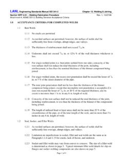
1 LANL Engineering Standards Manual ISD 341-2 Chapter 13, Welding & Joining Section WFP 2-01 Welding Fabrication Procedure Rev. 1, 10/27/06. Attachment 3, ASME , Gas Transmission & Distribution Piping ALIGNMENT and Acceptance Criteria JOINT FIT-UP AND ALIGNMENT . For piping systems that operate at hoop stress of less than 20% and the internal adjoining ends do not vary more than 1/8 in. and adequate penetration and fusion can be obtained no special treatment is necessary. If the offset is greater than 1/8 in. the following shall apply. For piping systems that operate at hoop stress of 20% or more of the Specified Minimum Yield Strength the following shall apply. If the internal adjoining ends do not vary more than 3/32 in. and adequate penetration and fusion can be obtained no special treatment is necessary.
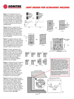
2 See Figure 14 of this Attachment. Where the nominal internal offset is greater than 3/32 in. and no access to the inside for welding, a transition shall be made to the thicker section not to exceed 30 (3:1. taper) or less than 15 (1 :1 taper). See Figure 15 of this Attachment. Where the nominal internal offset is greater than 3/32 in. but does not exceed the thinner section and there is access to the inside for welding, the transition may be made with a tapered weld or transition as described in paragraph shall be performed. See Figure 15 of this Attachment. Where the nominal internal offset is more than the thinner section and there is access for welding, the transition may be made with taper cut or by a combination taper weld to the thinner section see Figure 15 and taper cut from that point as shown in Figure 15 of Attachment.
3 Where the external offset does not exceed t of the thinner section, the transition may be made by welding as shown by Figure 15 of this Attachment, provided the angle of the rise of the weld surface does not exceed 30 (3:1 taper) and both bevel edges are properly fused. Where the is an external offset exceeding the thinner section, that portion of the offset over t shall be tapered as shown in Figure 15 of this Attachment. The root opening and FIT-UP tolerances shall be as specified in the weld JOINT design in this Attachment as applicable. If the tolerances cannot be achieved, the end preparations may be built up by welding (with an approved WPS or WTS) or re-prepped by machining or grinding. Parts to be joined by a tee or fillet weld shall be brought into as close contact as is practicable.
4 The maximum gap between these parts shall not exceed 1/8 in. If the separation is greater than 1/16 in., each leg of the fillet weld shall be increased by the amount of separation. Page 1 of 8. LANL Engineering Standards Manual ISD 341-2 Chapter 13, Welding & Joining Section WFP 2-01 Welding Fabrication Procedure Rev. 1, 10/27/06. Attachment 3, ASME , Gas Transmission & Distribution Piping ALIGNMENT and Acceptance Criteria In assembly of socket weld joints, the pipe or tube shall be withdrawn a distance of approximately 1/16 in. away from contact between the end of the pipe and the face of the shoulder of the socket. In sleeve-type joints without an internal shoulder, there shall be a distance of approximately 1/16 in. between the butting ends of the pipe or tube and the butting ends shall be centered in the sleeve.
5 Note: Gap inserts (Gapalets or equivalent). and approved shims may be used with prior approval from the design engineer or LANL. Welding Program Administrator. ACCEPTANCE CRITERIA FOR COMPLETED WELDS. Butt Welds The quality of welding shall be checked visually on a sampling basis (see paragraph ) and defective welds shall be removed and replaced or repaired in accordance with the original WPS or WTS as applicable The quality of welds shall also be examined by nondestructive examination (NDE). methods. The NDE method may consist of radiography, magnetic particle or any other acceptable NDE method. The following is the minimum number of welds that shall be selected on a random basis from each day's production. Each weld shall be examined visually and accepted prior to being examined by an NDE method.
6 Each weld selected shall be examined for the entire circumference. If only part of the weld circumference is to be examined, the responsible engineer or LANL WPA shall approve the selection process prior to its implementation. The same criteria shall be applied to piping systems double ending at railheads or yards. 10% of welds in Location Class 1. 15% of welds in Location Class 2. 40% of welds in Location Class 3. 75% of welds in Location Class 4. 100% of welds in compressor stations, and at major or navigable river crossings, major highway crossings and railroad crossings, if practical, but in any case not less than 90%. All tie-in welds not subjected to a positive pressure proof test shall be examined. See page 9 for pipe system classification criteria.
7 Welds that are examined visually shall meet the visual acceptance standards of API. 1104. See WFP 2-03, Welding Fabrication Procedure for API 1104 Welding of Pipelines and Related Facilities section of this program. The results of visual examination shall be used to control the quality of the welding. Page 2 of 8. LANL Engineering Standards Manual ISD 341-2 Chapter 13, Welding & Joining Section WFP 2-01 Welding Fabrication Procedure Rev. 1, 10/27/06. Attachment 3, ASME , Gas Transmission & Distribution Piping ALIGNMENT and Acceptance Criteria When radiography or other NDE methods are employed, the procedure shall meet the requirements of API 1104. When the pipe size is less NPS 6 or the project involves a limited number of welds that NDE examination would be impractical, and the system is intended to operate at 40% or less of specified yield strength, then provisions of paragraphs , , and are not mandatory, provided the welding is examined visually by a qualified (AWS CWI or equivalent) inspector.
8 In addition to the NDE requirements qualified (AWS CWI or equivalent) weld inspection personnel continually (surveillance basis) control the quality of the in- process welding. As-welded surfaces are permitted; however, the surface of welds shall be sufficiently free from coarse ripples, grooves, overlaps, abrupt ridges, and valleys. The surface condition of the finished welds shall be suitable for the proper interpretation of radiographic and other nondestructive examinations when nondestructive examinations are required. Surface preparation, when required for RT, PT, MT, or UT shall have a minimum of a 250 RMS or equivalent finish. In those cases where there is a question regarding the surface condition on the radiographic film, the film shall be compared (overlay) to the actual weld surface for interpretation and determination of acceptability.
9 Socket and Fillet Welds As-welded surfaces are permitted; however, the surface of welds shall be sufficiently free from coarse ripples, grooves, overlaps, abrupt ridges, and valleys. The surface condition of finished socket and fillet welds shall be suitable for the proper interpretation of nondestructive examinations, where required. Surface preparation, when required for PT, MT, or UT shall have a minimum of a 250 RMS. or equivalent finish. Socket and fillet welds may vary from convex to concave. The size of a fillet weld is determined as shown in the Figure 12. Typical minimum fillet weld details for slip-on flanges and socket-welding components are also contained in Figure 16 of this Attachment. Page 3 of 8. LANL Engineering Standards Manual ISD 341-2 Chapter 13, Welding & Joining Section WFP 2-01 Welding Fabrication Procedure Rev.
10 1, 10/27/06. Attachment 3, ASME , Gas Transmission & Distribution Piping ALIGNMENT and Acceptance Criteria Figure 12. FILLET WELD PROFILES AND DIMENSIONS. Page 4 of 8. LANL Engineering Standards Manual ISD 341-2 Chapter 13, Welding & Joining Section WFP 2-01 Welding Fabrication Procedure Rev. 1, 10/27/06. Attachment 3, ASME , Gas Transmission & Distribution Piping ALIGNMENT and Acceptance Criteria Figure 14. PREPARATION FOR BUTT WELDING. Page 5 of 8. LANL Engineering Standards Manual ISD 341-2 Chapter 13, Welding & Joining Section WFP 2-01 Welding Fabrication Procedure Rev. 1, 10/27/06. Attachment 3, ASME , Gas Transmission & Distribution Piping ALIGNMENT and Acceptance Criteria Figure 15. Acceptable Design for Unequal Wall Thickness Page 6 of 8.