Transcription of 1 Air-conditioning fundamentals - Elsevier
1 1 Air-conditioning fundamentalsThe aim of this chapter is to: Give an overview of the historical development of the heating and ventilation system andintroduction of the Air-conditioning (A/C) system. Provide the reader with a case study on the design and optimisation of an Air-conditioning (A/C) system. Enable the reader to understand the fundamental principles and operation of the heating ,cooling, ventilation and Air-conditioning system. Introduce the possible replacement refrigerant/system to History of automotive Air-conditioning systemsThe early history of transportation systems starts mainly with the horse drawn carriage. This waseventually surpassed by the invention of the automobile. Early automobiles had cabin spacesthat were open to the outside environment. This means that the occupants had to adjust thereclothing to allow for different weather conditions.
2 Closed cabin spaces were eventually intro-duced which required heating , cooling and ventilating to meet customer expectations. Earlyheating systems included heating clay bricks and placing them inside the vehicle or using simplefuel burners to add heat to the vehicle s interior. Ventilation inside the vehicle was achievedthrough opening or tilting windows or the windscreen; vents were added to doors and bulkheadto improve air circulation and louvered panels were the equivalent to our modern air ducts. Airflow was hard to control because it was dependent upon the vehicle speed and sometimes wouldallow dirty, humid air which contained fumes from the engine compartment. Cooling could be assimple as having a block of ice inside the vehicle and allowing it to melt! Eventually a number ofdesign issues were overcome, these included air vents at the base of the windscreen for naturalflow ventilation and electric motors to increase the flow at low speeds.
3 Eventually heat exchan-gers were introduced which used either the heat from the exhaust system or water from the cool-ing system as a source, to heat the inside of the vehicle cabin. Early cabin cooling systems wereaftermarket sourced and worked on evaporative cooling. They consisted of a box or cylinder fit-ted to the window of the vehicle. The intake of the unit would allow air to enter from outside andtravel through a water soaked wire mesh grill and excelsior cone inside the unit. The water wouldevaporate due to absorbing the heat in the air and travel through the outlet of the unit whichacted as a feed to the inside of the vehicle. The water was held in a reservoir inside the unit andhad to be topped up to keep the cone wet otherwise the unit would not operate. The air enteringthe vehicle would be cool if the relative humidity of the air entering the unit was low.
4 If the rela-tive humidity of the air was high then the water could not evaporate. When the unit was workingeffectively it would deliver cool saturated water vapour to the inside of the vehicle which raisedthe humidity levels. These units were only really effective in countries with very low 3/18/06 10:42 PM Page 12 Automotive Air-conditioning and Climate Control SystemsIn 1939 Packard marketed the first mechanical automotive A/C system which worked on aclosed cycle. The system used a compressor, condenser, receiver drier and evaporator (fittedinside the boot/trunk) to operate the system. The only system control was a blower marketing campaign included: Forget the heat this summer in the only air-conditionedcar in the world. The major problem with the system was that the compressor operated continu-ously (had no clutch) and had to have the belt removed to disengage the system which was gener-ally during the winter months.
5 Over the period 1940 41 a number of manufacturers made vehicleswith A/C systems but these were in small volume and not designed for the masses. It wasn t untilafter World War II that Cadillac advertised a new feature for the A/C system that located the A/Ccontrols on the rear parcel shelf, which meant that the driver had to climb into the back seat toswitch the system off. This was still better than reaching under the bonnet/hood to remove thedrive belt. In 1954 55 Nash-Kelvinator introduced Air-conditioning for the mass market. It wasan A/C unit that was compact and affordable with controls on the dash and an electric design and optimisation of an Air-conditioning systemCase study the air handling systemExperimental approachIn the past, the only way to evaluate a proposed air handling system design was to build a prototype and test it in the laboratory.
6 The air handling components were placed on a test stand,conditioned air was supplied at the inlet and the airflow and temperature distribution at crit-ical locations were measured. This approach takes a considerable amount of time and requiresthe construction of expensive prototypes. In addition, it provides little or no understanding ofwhy a design performed the way it did. In particular, testing is unable to detect details of recir-culating areas, turbulence, temperature stratification and constrictions that adversely impactperformance and pressure loss. In addition, the performance of the system usually needs to beevaluated in many different configurations. For example, it sometimes is necessary to evaluatethe air handling system in different modes of operation vent, floor, defrost and mixed ateach of eight different temperature methods of designThe design process of modern vehicle systems improved with the introduction of ComputerAided Design (CAD), Computer Aided Engineering (CAE) and Computer Aided Manufac-turing (CAM).
7 CAD allows designs to be generated and visually appreciated on a components can be shared among manufacturers and suppliers to ensure that compon-ents assemble correctly. Designs can be sent to clients for verification and feedback. Designscan be modified and rechecked within short periods of time in a number of different formats, an STL file (stereolithography). Complex parts and assemblies can often be manufacturedvery quickly using rapid prototyping facilities (CAM). CAD also includes the facility to providevirtual testing. This is generally provided using additional modules or add-ins converting CADto CAE. A number of secondary schools in the UK have the use of Solidworks as a CAD pack-age for their technology departments which include add-in modules like Cosmos Works forFinite Element Analysis and Computational Fluid Dynamics.
8 Finite Element Analysis (FEA)is basically mechanical stress analysis and Computational Fluid Dynamics (CFD) analyses theflow of a fluid like air through or over complex geometry. These additional features are all com-puter based and use mathematical equations built into the software to predict variables likethe stress distribution of a component or assembly (FEA) or the flow of air through an air vent(CFD). All these tests would have originally been carried out manually with continual adjust-ments being made to a model to optimise 3/18/06 10:42 PM Page 2 Air-conditioning fundamentals 3 The processThe A/C system begins life as an idea driven by consumer needs or sometimes governmentlegislation. This leads to a specification. The specification will include minimum performancerequirements, temperatures, control zones, flow rates etc.
9 This will lead to a number of conceptdesigns. The designs will have a number of computer generated models which will be presentedas possible solutions to the original specification. These need to be tested for their testing using CFD may include fluid velocity (air flow), pressure values and tem-perature distribution. Using CFD enables the analysis of fluid through very complex geom-etry and boundary conditions. The geometry typically includes ducts that expand and contract,change from round to square cross-sections, go through complex curves throughout their length,and have many branches and internal part of the analysis, a designer may change the geometry of the system or the boundaryconditions such as the inlet velocity, flow rate etc. and view the effect on fluid flow is an efficient tool for generating parametric studies with the potential of significantlyreducing the amount of experimentation required to optimise the performance of a fan performance curve can be inputted into a model.
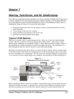
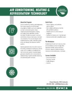
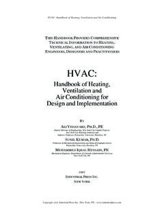
10 Without this feature, the user has toguess the flow within the enclosure, calculate the pressure using CFD and see if it matches theFigure generated model designed using CAD (without ducting and vents)( 2005 Visteon All Rights Reserved)Figure pressure loss predicted by CFD( 2005 Visteon All Rights Reserved) 3/18/06 10:42 PM Page 34 Automotive Air-conditioning and Climate Control SystemsFigure showing flow field in an air handling system( 2005 Visteon All Rights Reserved)Figure flow optimisation( 2005 Visteon All Rights Reserved)fan s characteristics. If the pressure doesn t match, then another guess has to be made. Normally,at least three iterations (test runs) are required to make a software enters the fan curve directly into the model. Each analysis run then interactswith the fan curve to determine the precise operating conditions of the fan as part of the 3/18/06 10:42 PM Page 4 Air-conditioning fundamentals 5analysis.