Transcription of 1 Basic Principles of - Mike Holt Enterprises
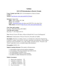
1 mike holt Enterprises , Inc. ( )3U N I T1 Basic Principles of Motor ControlsUnit 1 IntroductionThis unit discusses the Basic concepts of motor control, including motor control language and the types of wiring diagrams Control CircuitsMotor control circuits are an effective way to reduce cost by using smaller wire and reduced-amperage devices to control a motor. Imagine trying to wire a pushbutton station for a 100A motor using 3 AWG conductors. Many smaller motors use the same size conductors for both control and power circuits, but as the horsepower increases it becomes impractical to do so, Figure 1 1. Motor control circuits are often con-nected to lower voltages than the motor they control to make it safer for operators and maintenance personnel.
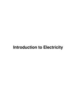
2 A motor control circuit , for the most part, is simply a switch (or group of switches) and a motor. If you keep the word switch in mind, it helps keep the intimidat-ing subject of motor control in its proper context. For example, the following can be considered motor controls:A time clock that operates a pool or sprinkler pump is nothing more than an automatic switch. At a preset time, a set of contacts open or close (turn off or on). Figure 1 2An automatic garage door opener uses a radio signal to operate a switch that activates a garage door in much Figure 1 1 Figure 1 24 mike holt s Illustrated Guide to Understanding Basic Motor ControlsUnit 1 basic principles of Motor Controlsdevice will operate to open the circuit because of the increased heat caused by the current running through it.
3 A magnetic starter or other motor controllers may include overload devices, or they may be an integral part of the motor, particularly with small s Comment: Short circuits and ground faults aren t considered are two Basic designs of motor control equip-ment, NEMA and (National Electrical Manufacturers Association). NEMA is a trade association for manufacturers of elec-trical equipment and supplies. NEMA standards spec-ify motor horsepower (hp) ratings, speeds, motor frame sizes and dimensions, motor torques, motor starter size ratings, and enclosure products are typically heavy duty, can be used in a broad range of applications, and some start-ers can be maintained and repaired.
4 For these reasons, they re often more expensive than IEC motor starters. NEMA-rated motors and motor controllers are the type most commonly used in North (International Electrotechnical Commission). IEC is an international standards organization. IEC motor starters are often less expensive, smaller in size, are tai-lored for specific motor performance requirements, and the selection of the right starter for each application is very important. IEC-rated motor controllers are widely used in Europe and Motor Control LanguageElectrical symbols, words, and line diagrams provide the information necessary to understand the operation of motor control circuits. Used together, they create a the same manner as a typical up-down pushbutton motors are controlled by computerized con-trol systems, solid-state logic controls, or program-mable logic controllers (PLCs).
5 The fundamentals of control systems still apply. The PLC controls an exter-nal output based on the logic of a control program, and that output controls the motor or groups of motors by using a magnetic starter, and in some cases additional relays. PLCs and other solid-state control devices were originally invented to provide less expensive replace-ments for older automated systems that used large num-bers of relays and mechanical timers. In some cases, a single PLC can replace thousands of relays resulting in less expensive wiring systems that offer greater flexibility in control s Comments: In industrial processes, the control of pressure, flow, speed, temperature, and other items are essential for efficient productivity and safety.
6 Devices such as solid-state sensors, static controls, solid-state relays, and programmable controls can provide very precise control for an industrial process. Although the subject of solid-state controls isn t covered in detail in this textbook, the concepts are very simi-lar to other motor controls in that they essentially use switches to control motors. Many experts agree that the best way to learn about motor controls is to start with the standard control meth-ods covered in this textbook. This statement also applies when electronic controls are the subject being control circuits include motor overload protec-tion devices.
7 Traditional overload (OL) protectors oper-ate on the relationship between heat and current. As current increases, heat increases. If an overload device is rated 10A, and the current exceeds that rating, the OL mike holt Enterprises , Inc. ( )5 Basic Principles of Motor ControlsUnit 1(1) Ladder Diagrams (Figure 1 4)Ladder diagrams are also called line diagrams or elementary diagrams. They re used to represent the function of the control circuit and the associated devices, but don t show the components of the con-trol circuit in their actual positions. As control cir-cuits become more complex, a ladder diagram can be less complicated to read than a wiring or connec-tion diagram.
8 For example, in Figure 1 4, notice the set of contacts marked M under the start pushbutton. The M contacts marked 2 and 3 are actually located in the motor starter fairly close to the coil, as shown in Figure 1 3B, and the normal physical appearance of these contacts often look as shown in Figure 1 3C. (Notice that all three examples of the M contacts are shown with a blue background in Figure 1 3.) The ladder diagrams in Figures 1 4 and 1 5 illustrates electrical function, showing the M contacts in paral-lel with the start pushbutton to form what s called a holding circuit . The physical location of the M con-tacts isn t shown in the ladder of motor control language that s used to trans-fer information and ideas quickly and symbols in motor control schematics represent devices, power conductors, control conductors, con-ductor connections and terminals, and sometimes the motor words, phrases, and abbreviations in a schematic are generally accepted terms that represent functions, describe actions, and list sequences of operation.
9 In many cases, the symbols and words have a similarity to the items they represent. The Basic types of schemat-ics are shown in Figure 1 3. Parts A, B, and C of that figure illustrate three different methods of representing the same control 1 3 Figure 1 46 mike holt s Illustrated Guide to Understanding Basic Motor ControlsUnit 1 basic principles of Motor ControlsDifferent manufacturers of control devices, as well as books about motor controls, use different methods of showing the control circuit wiring. For example, in Figure 1 3B1, the control wiring from the start-stop pushbutton station runs to the actual connection points 1, 2, and 3. As the wiring diagrams become more com-plicated, the optional method shown in Figure 1 3B2 is frequently used to show the connection points for the start-stop pushbutton station.
10 Here, in Figure 1 6, instead of running the control wires to the actual con-nection point, arrowed lines represent connections to be made by the installer. Author s Comments: Many times you see plain lines (no arrows) with num-bers to indicate connections to be made by the installer. We use both methods in this textbook. Many of the components and symbols used in ladder diagrams and wiring diagrams are the same. In order to make schematics easier to read, some manufactur-ers combine the two types of diagrams together. Some equipment comes with both ladder diagrams and wiring 1 5 shows a more complicated version of a ladder diagram.