Transcription of 1 INTRODUCTION IJSER
1 International Journal of Scientific & Engineering Research, Volume 4, Issue 5, May-2013 1560 ISSN 2229-5518 IJSER 2013 DESIGN OF COOLING TOWER B Bhavani Sai1, I Swathi2, K S L Prasanna3, K Srinivasa Rao4 Abstract This paper presents detailed methodology of a Induced draft cooling tower of counter flow type in which its efficiency, effectiveness, char-acteristics are calculated. The technical data has been taken from a mechanical draft cooling tower. Cooling towers are heat removal devices used to transfer process waste heat to the atmosphere.
2 Cooling towers make use of evaporation whereby some of the water is evaporated into a moving air stream and subsequently discharged into the atmosphere. As a result, the remainder of the water is cooled down significantly. Index Terms Cooling tower, Types of cooling towers, Design of cooling tower, Different types of losses, characteristics of cooling tower, efficiency, eff ectiveness.. 1 INTRODUCTION A cooling tower is a semi-enclosed device for evaporative cool-ing of water by contact with air.
3 It is a wooden, steel or con-crete structure and corrugated surfaces or baffles or perforated trays are provided inside the tower for uniform distribution and better atomization of water in the tower. The hot water coming out from the condenser is fed to the tower on the top and allowed to tickle in form of thin drops [1] . The air flows from bottom of the tower or perpendicular to the direction of water flow and then exhausts to the atmosphere after effective cooling. To prevent the escape of water particles with air, draft eliminators are provided at the top of the tower.
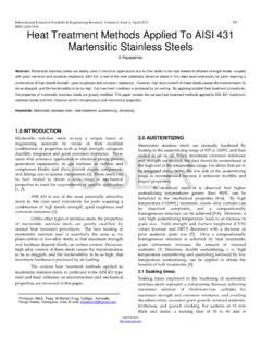
4 SCHEMATIC DIAGRAM OF COOLING TOWER Cooling tower reduces temperature of circulating water so that water may be used in heat exchange equipment and con-densers [5]. Cooling towers are equipment devices commonly used to dissipate heat from power generation units, water-cooled refrigeration, air conditioning and industrial processes. Cooling towers offer an excellent alternative particularly in locations where sufficient cooling water cannot be easily ob-tained from natural sources or where concern for the envi-ronment imposes some limits on the temperature at which cooling water can be returned to the surrounding[1].
5 There are several important factors that govern the operation of cool-ing tower: - The dry-bulb and wet-bulb temperatures of the air - The temperature of warm water - The efficiency of contact between air and water in terms of the volumetric mass transfer coefficient and the contact time between the air and the water - The uniformity of distribution of the phases within the tower - The air pressure drop - The desired temperature of the cooled water. Air might enter the tower driven by a density gradient (natu-ral draft), might be pushed into the tower (forced draft) at the base or drawn into the tower (induced draft) assisted by a fan.
6 VARIOUS TYPES OF COOLING TOWERS: The cooling tower might be classified into several types, but they are broadly categorized by following considerations: 1. Whether there is direct or indirect contact 2. The mechanism used to provide the required airflow 3. The relative flow paths of air and water 4. The primary materials of construction 5. the type of heat transfer media applied 6. The tower s physical shape IJSERI nternational Journal of Scientific & Engineering Research, Volume 4, Issue 5, May-2013 1561 ISSN 2229-5518 IJSER 2013 GENERAL CLASSIFICATION OF COOLING TOWERS Classification based on air draft: 1) Atmospheric tower 2) Natural draft tower 3)Mechanical draft tower Mechanical draft tower: Mechanical draft towers have large fans to force or draw air through circulated wate [2].
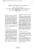
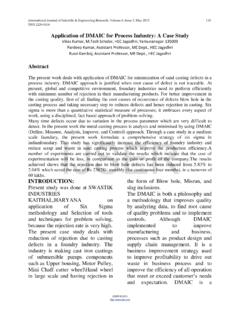
7 There are two different classes of mechanical draft cooling towers a. Forced draft: It has one or more fans located at the tower bottom to push air into the tower [3]. During operation, the fan forces air at a low velocity horizontally through the packing and then vertically against the downward flow of the water that occurs on either side of the fan. The drift elimina-tors located at the top of the tower remove water entrained in the air FORCED DRAFT COOLING TOWER Draft: A mechanical draft tower with a fan at the discharge which pulls air through tower [1] [6].
8 The fan induces hot moist air out the discharge. This produces low entering and high exiting air velocities, reducing the possibil-ity of recirculation in which discharged air flows back into the air intake. IN DUCED DRAFT COOLING TOWER DESIGN CONSIDERATION FOR COOLING TOWERS: Once a tower characteristic has been established between the plant engineer and the manufacturer, the manufacturer must design a tower that matches the value [7]. The required tower size will be a function of: 1. Cooling range 2. Approach to wet bulb temperature 3.
9 Mass flow rate of water 4. Wet bulb temperature 5. Air velocity through tower or individual tower cell 6. Tower height Other design characteristics to consider are fan horse power, pump horse power make-up water source, fogging abatement, and drift eliminator [4]. CALCULATIONS FOR COOLING TOWER: Inlet temp of air (t1)-270c Outlet temp of air (t2)-360c Inlet temp of water (T1)-400c Outlet temp of water (T2)-320c Wet bulb temp-280c Mass Flow Rate (v) 10 m3/hr. VALUES FROM PSYCHOMETRIC CHART.
10 - Specific volume of air at inlet (VS1) - m3/kg Specific volume of air at outlet (VS2) - m3/kg Specific humidity of air at inlet (W1) - kg/kg Specific humidity of air at outlet (W2) kg/kg Enthalpy of water at inlet temp (HW1) kj/kg Enthalpy of water at outlet temp (HW2) kj/kg Enthalpy of air at inlet temp (Ha1) 73 kj/kg IJSERI nternational Journal of Scientific & Engineering Research, Volume 4, Issue 5, May-2013 1562 ISSN 2229-5518 IJSER 2013 Enthalpy of air at outlet temp (Ha2) 115 kj/kg COOLING TOWER APPROACH: CTA= outlet temp of water-wet bulb temp=320c-280c=4 COOLING TOWER RANGE: CTR=inlet temp of water-outlet temp of water=400c-320c=8 MASS OF WATER: MW=Mass flow rate * density of water=10*10000 kg/hr.