Transcription of []10 5 10Q 10(Q2 1 - Connecticut
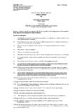
1 Storm Drainage Systems Appendix C Water Quality Flow (WQF) and Flow Diversion Guidance Water Quality Flow Calculation The water quality flow (WQF) is the peak flow rate associated with the water quality design storm. This section describes the recommended procedures for calculating the water quality flow for the design of: Pre-manufactured stormwater treatment devices ( hydrodynamic separators, catch basin inserts, and media filters). Flow diversion structures for off-line stormwater treatment practices The WQF should be calculated using the water quality volume (WQV) described in Chapter 10. This WQV, converted to watershed inches, should be substituted for the runoff depth (Q) in the Natural Resources Conservation Service (NRCS) (formerly Soil Conservation Service), TR-55. Graphical Peak Discharge Method. The procedures are based on the approach described in Claytor and Schueler, 1996.
2 1. Compute the NRCS Runoff Curve Number (CN) using the following equation, or graphically using Figure 2-1 from TR-55 (USDA, 1986) (reproduced below): 1000. CN =. [. 10 + 5P + 10Q 10(Q 2 + )1 / 2 ] (English Units Only). where: CN = Runoff Curve Number P = design precipitation, inches (1" for water quality storm). Q = runoff depth (in watershed inches). Q =. [WQV(acrefeet )]X [12(inches / foot )]. DrainageArea(acres). December 2003 ConnDOT Drainage Manual Storm Drainage Systems Solution of runoff equation (Figure 2-1 TR55). 2. Compute the time of concentration (tc) based on the methods described in Chapter 3 of TR-55. A minimum value of hours (10 minutes) should be used. For sheet flow, the flow path should not be longer than 300 feet. 3. Using the computed CN, tc, and drainage area (A) in acres, compute the peak discharge for the water quality storm ( , the water quality flow), based on the procedures described in Chapter 4.
3 Of TR-55. Read initial abstraction (Ia) from Table 4-1 in Chapter 4 of TR-55 (reproduced below); compute Ia/P. ConnDOT Drainage Manual December 2003. Storm Drainage Systems Ia values for runoff curve numbers (Table 4-1 TR55). Curve Ia Curve Ia number (in) number (in). Read the unit peak discharge (qu) from Exhibit 4-III in Chapter 4 of TR-55 (reproduced below). for appropriate tc December 2003 ConnDOT Drainage Manual Storm Drainage Systems Unit peak discharge (qu) for SCS type III rainfall distribution (Exhibit 4-III TR55). Substituting the water quality volume (WQV), converted to watershed inches, for runoff depth (Q), compute the water quality flow (WQF) from the following equation: WQF = (qu)(A)(Q). where: WQF = water quality flow (cfs) (English units only). qu = unit peak discharge (cfs/mi2/inch). A = drainage area (mi2).
4 Q = runoff depth (in watershed inches). Q =. [WQV(acrefeet ]X [12(inches / foot ]. DrainageArea(acres). ConnDOT Drainage Manual December 2003. Storm Drainage Systems Flow Diversion Structures Flow diversion structures, also called flow splitters, are designed to deliver flows up to the design water quality flow or water quality volume to off-line stormwater treatment practices. Flow in excess of the WQF or WQV are diverted around the treatment facility with minimal increase in head at the flow diversion structure to avoid surcharging the treatment facility under higher flow conditions. Flow diversion structures are typically manholes or vaults equipped with weirs, orifices, or pipes to bypass excess runoff. The following general procedures are recommended for design of flow diversion structures: Locate the top of the weir or overflow structure at the maximum water surface elevation associated with the WQF, or the water surface elevation in the treatment practice when the entire WQV is being held, whichever is higher.))
5 Determine the diversion structure dimensions required to divert flows in excess of the WQF. using standard equations for a rectangular sharp-crested weir, uniform flow in pipes or channels, or orifice depending on the type of diversion structure. Provide sufficient freeboard in the stormwater treatment practice and flow splitter to accommodate flow over the diversion structure. Limit the maximum head over the flow diversion structure to avoid surcharging the stormwater treatment practice under high flow conditions. Design diversion structures to withstand the effects of freezing, frost in foundations, erosion, and flotation due to high water conditions. These structures should be designed to minimize clogging potential and to allow for ease of inspection and maintenance. December 2003 ConnDOT Drainage Manual
