Transcription of 10.8 Outlet Hydraulics 10.8.1 General - Connecticut
1 Storage Facilities 2000 ConnDOT Drainage Outlet GeneralA stage-discharge (performance) curve defines the relationship between the depth of water andthe discharge or outflow from a storage facility. A typical storage facility will have both aprincipal and an emergency Outlet . The principal Outlet is usually designed with a capacitysufficient to convey the design flood without allowing flow to enter the emergency spillway. Thestructure for the principal Outlet will typically consist of a pipe culvert, weir, orifice, or otherappropriate hydraulic control device. Multiple Outlet control devices are often used to providedischarge controls for multiple frequency of a composite stage-discharge curve requires consideration of the dischargerating relationships for each component of the Outlet structure.
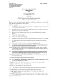
2 The following sections presentdesign relationships for typical Outlet OrificesFor a single orifice as illustrated in Figure 10-11 (a), orifice flow can be determined usingequation )H g (2 A C = ( )where: Q= the orifice flow rate, m3/s (ft3/s)Co= discharge coefficient ( - )Ao= area of orifice, m2 (ft2)Ho= effective head on the orifice measured from the centroid of the opening, m (ft)g= gravitational acceleration, m/s2 ( ft/s2)If the orifice discharges as a free outfall, then the effective head is measured from the centerlineof the orifice to the upstream water surface elevation. If the orifice discharge is submerged, thenthe effective head is the difference in elevation of the upstream and downstream water latter condition of a submerged discharge is shown in Figure 10-11(b).For square-edged, uniform orifice entrance conditions, a discharge coefficient of should beused.
3 For ragged edged orifices, such as those resulting from the use of an acetylene torch to cutorifice openings in corrugated pipe, a value of should be circular orifices with Co set equal to , the following equation results:H D K = o( )where: Kor= in units ( in English units)D= orifice diameter, m (ft)Pipes smaller than m (1 ft) in diameter may be analyzed as a submerged orifice as long asHo/D is greater than Pipes greater than m (1 ft) in diameter should be analyzed as adischarge pipe with headwater and tailwater effects taken into account, not just as an Storage FacilitiesConnDOT Drainage ManualOctober 2000 Figure 10-11 Definition Sketch for Orifice FlowStorage Facilities 2000 ConnDOT Drainage ManualFlow through multiple orifices (see Figure 10-11(c)) can be computed by summing the flowthrough individual orifices.
4 For multiple orifices of the same size and under the influence of thesame effective head, the total flow can be determined by multiplying the discharge for a singleorifice by the number of openings. The procedure is demonstrated in the following example:Example 10-4 Given:Given the orifice plate in Figure 10-11 (c) with a free discharge and:orifice diameter = 25 mm ( in)H1= m ( ft)H2= m ( ft)H3= m ( ft)Find: Total discharge through the orifice :Using a modification of equation for multiple orifices,Qi=K D2 (Hi) NiQi= ( ) ( )2 (Hi ) Ni = Hi NiQ1= ( ) (3) = ( ) (4) = ( ) (3) = total=Q1 + Q2 + Q3= m3/s ( ft3/s) Storage FacilitiesConnDOT Drainage ManualOctober 2000 Example 10-5 Given:Given the circular orifice in Figure 10-11(a) with:orifice diameter = m ( ft)orifice invert= m ( ft)discharge coeff.
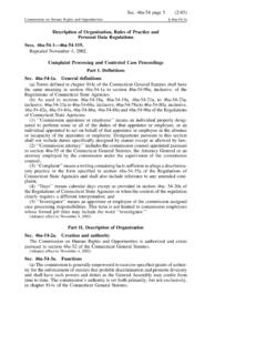
5 = : The stage - discharge rating between 10 m ( ft) and m ( ft).Solution:Using equation with D = m yields the following relationship between theeffective head on the orifice (Ho) and the resulting discharge:Q= -D/2 The solution of this equation in table form is as follows:Stage Discharge TabulationDEPTHSTAGEDISCHARGE(meters)(fe et)(meters)(feet)(m3/s)(ft3/s) Facilities 2000 ConnDOT Drainage for sharp-crested, broad-crested, V-notch, and proportional weirs are provided inthe following sections:Sharp Crested WeirsTypical sharp crested weirs are illustrated in Figure 10-12. Equation provides thedischarge relationship for sharp crested weirs with no end contractions (illustrated in Figure 12a).H C = wc sL( )where: Q= discharge, m3/s (ft3/s)L= horizontal weir length, m (ft)H= head above weir crest excluding velocity head, m (ft)CSCW= + (H/Hc) [ + (H/Hc) in English units]As indicated above, the value of the coefficient CSCW is known to vary with the ratio H/Hc (seeFigure 10-12c for definition of terms).
6 For values of the ratio H/Hc less than , a constant CSCWof ( in English units) is often provides the discharge equation for sharp-crested weirs with end contractions(illustrated in Figure 10-12(b)). As indicated above, the value of the coefficient Cscw is known tovary with the ratio H/Hc (see Figure 10-13c for definition of terms). For values of the ratio H/Hcless than , a constant Cscw of ( in English units) is often ) H - L ( C = WC S( )Sharp-crested weirs will be effected by submergence when the tailwater rises above the weircrest elevation, as shown in Figure 10-12(d). The result will be that the discharge over the weirwill be discharge equation for a submerged sharp-crested weir is:) ) H / H ( - 1 ( Q = ( )where: Qs=submerged flow, m3/s (ft3/s)Qr= unsubmerged weir flow from equation or , m3/s (ft3/s)H1= upstream head above crest, m (ft)H2= downstream head above crest, m (ft)Flow over the top edge of a riser pipe is typically treated as flow over a sharp crested weir withno end constrictions.
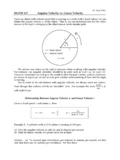
7 Equation should be used for this Storage FacilitiesConnDOT Drainage ManualOctober 2000 Figure 10-12 Sharp Crested WeirsStorage Facilities 2000 ConnDOT Drainage ManualExample 10-6 Figure 10-13 Riser PipeGiven:A riser pipe as shown in Figure 10-13 with the following characteristics:diameter (D)= m ( ft)crest elevation= m ( ft)weir height (Hc) = m ( ft)Find:The stage - discharge rating for the riser pipe between 10 m ( ft) and m ( ).Solution:Since the riser pipe functions as both a weir and an orifice (depending on stage), therating is developed by comparing the stage - discharge produced by both weir andorifice flow as follows:Using equation for orifices with D = m ( ft) yields the followingrelationship between the effective head on the orifice (Ho) and the resultingdischarge:Q=Kor D2 = ( )( )2 = equation for sharp crested weirs with CSCW = (H/Hc assumed lessthan ), and L = pipe circumference = m ( ft) yields the followingrelationship between the effective head on the riser (H) and the resulting discharge.
8 Q=CSCW L = ( )( ) = Storage FacilitiesConnDOT Drainage ManualOctober 2000 The resulting stage - discharge relationship is summarized in the following table:STAGEEFFECTIVEHEADORIFICE FLOWWEIR FLOW(m)(ft)(m)(ft)(m3/s)(ft3/s)(m3/s)(ft 3/s) Designates controlling flow condition, orifice or weir, producing the lowest discharge for a given stage defines thecontrolling relationship. As illustrated in the above table, at a stage of m ( ft) weir flowcontrols the discharge through the riser. However, at and above a stage of m ( ft),orifice flow controls the discharge through the WeirThe equation typically used for a broad-crested weir is:H L C = Q WC B ( )where: Q=discharge, m3/s (ft3/s)CBCW=broad-crested weir coefficient, - ( to )L=broad-crested weir length, m (ft)H=head above weir crest, m (ft)If the upstream edge of a broad-crested weir is so rounded as to prevent contraction and if theslope of the crest is as great as the loss of head due to friction, flow will pass through critical depthat the weir crest; this gives the maximum C value of For sharp corners on the broad crestedweir, a minimum value of should be used.
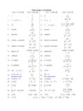
9 Additional information on C values as a functionof weir crest breadth and head is given in Table Facilities 2000 ConnDOT Drainage ManualTable 10-2 Broad-crested weir coefficient C values as a function of weir crest breadthand head (coefficient has units of ) (metric only)BREADTH OF CREST OF WEIR (m)Head(1)(m) (1)Measured at least Hc upstream of the Storage FacilitiesConnDOT Drainage ManualOctober 2000V-Notch WeirThe discharge through a v-notch weir is shown in Figure 10-14 and can be calculated from thefollowing equation:H ) 2 / ( tan 8 = ( )where: Q = discharge, m3/s (ft3/s) = angle of v-notch, degreesH = head on apex of v-notch, m (ft)Figure 10-14 V-notch WeirProportional WeirAlthough more complex to design and construct, a proportional weir may significantly reducethe required storage volume for a given site.
10 The proportional weir is distinguished from othercontrol devices by having a linear head-discharge relationship. This relationship is achieved byallowing the discharge area to vary nonlinearly with equations for proportional weirs are as follows:) 3 / a - (H b a 4 = ( )]) ay / (arctan [ ( ) - 1 = ( )where:Q = discharge, m3/s (ft3/s)H = head above horizontal sill, m (ft)Dimensions a, b, x, and y are as shown in Figure Facilities 2000 ConnDOT Drainage ManualFigure 10-15 Proportional Weir Discharge PipesDischarge pipes are often used as Outlet structures for detention facilities. The design of thesepipes can be for either single or multistage discharges. A single stage discharge system wouldconsist of a single culvert entrance system and would not be designed to carry emergency flows.