Transcription of 10 pA, Ultra Low Leakage and Quiescent Current, Load ...
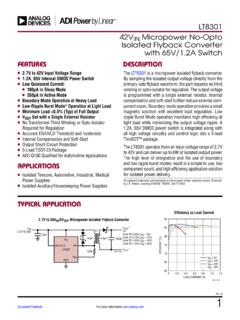
1 Siliconix S17-1318-Rev. E, 21-Aug-171 Document Number: 66597 For technical questions, contact: DOCUMENT IS SUBJECT TO CHANGE WITHOUT NOTICE. THE PRODUCTS DESCRIBED HEREIN AND THIS DOCUMENTARE SUBJECT TO SPECIFIC DISCLAIMERS, SET FORTH AT Low Leakage and Quiescent Current, 1 A Load Switch with Reverse BlockingDESCRIPTIONThe SiP32431 is an Ultra low Leakage and Quiescent currentslew rate controlled high side switch with reverse blockingcapability. The switch is of a low ON resistance p-channelMOSFET that supports continuous current up to 1 A. The SiP32431 operates with an input voltage from V V. The SiP32431 features low input logic level to interface withlow control voltage from microprocessors. This device has avery low operating current , typically 10 pA at V SiP32431 is available in lead (Pb)-free package optionsincluding 6 pin SC70-6, and 4 pin TDFN4 mm x mmDFN4 packages.
2 The operation temperature range isspecified from -40 C to +85 C. The SiP32431 compact package options, operation voltagerange, and low operating current make it a good fit forbattery power V to V input voltage range No bias power rail required Low on-resistance RDS(on),typically 105 m at 5 V and 135 m at 3 Vfor TDFN4 mm x mm package Typical 147 m at 5 V and 178 m at 3 V forSC70-6 package Slew rate controlled turn-on time: 100 s Ultra low Leakage and Quiescent current :- VIN Quiescent current = nA- VIN shutdown Leakage = nA Reverse blocking capability SC70-6 and TDFN4 mm x mm packages Material categorization: for definitions of complianceplease see Wireless sensor network Smart meters Wearable Internet of things Portable medical devices Security systems Battery powered devices Portable InstrumentsTYPICAL APPLICATION CIRCUIT Fig.
3 1 - SiP32431 Typical Application CircuitNotes x = lot code -GE3 denotes halogen-free and RoHS-compliant Please use the SiP32431DR3-T1GE3 to replace SiP32431DR3-T1-E3 AvailableORDERING INFORMATIONTEMPERATURE RANGEPACKAGEMARKINGPART NUMBER-40 C to +85 CSC70-6 MAxxSiP32431DR3-T1GE3 TDFN4 mm x mmDxSiP32431 DNP3-T1GE4 SiP32431 INVOUTOUTVINGND GND GND ON/OFF ON/OFF C1 FIN Siliconix S17-1318-Rev. E, 21-Aug-172 Document Number: 66597 For technical questions, contact: DOCUMENT IS SUBJECT TO CHANGE WITHOUT NOTICE. THE PRODUCTS DESCRIBED HEREIN AND THIS DOCUMENTARE SUBJECT TO SPECIFIC DISCLAIMERS, SET FORTH AT Device mounted with all leads and power pad soldered or welded to PC boardb. Derate mW/ C above TA = 70 Cc.
4 Derate mW/ C above TA = 70 C, see PCB layoutStresses beyond those listed under "Absolute Maximum Ratings" may cause permanent damage to the device. These are stress ratings only, and functional operationof the device at these or any other conditions beyond those indicated in the operational sections of the specifications is not implied. Exposure to absolute maximumrating / conditions for extended periods may affect device reliability. ABSOLUTE MAXIMUM RATINGSPARAMETER LIMITUNIT Supply input voltage (VIN) to +6 VEnable input voltage (VON/OFF) to +6 Output voltage (VOUT) to VIN + continuous switch current (Imax.)SC70-6 mm x pulsed current (IDM) VIN(pulsed at 1 ms, 10 % duty cycle)VIN V3 VIN < rating (HBM)4000 VJunction temperature (TJ)-40 to +125 CThermal resistance ( JA) a6 pin SC70-6 b220 C/W4 pin TDFN4 mm x mm c170 Power dissipation (PD) a6 pin SC70- 6 b250mW4 pin TDFN4 mm x mm c324 RECOMMENDED OPERATING RANGEPARAMETER LIMITUNIT Input voltage range (VIN) to temperature range-40 to +85 Siliconix S17-1318-Rev.
5 E, 21-Aug-173 Document Number: 66597 For technical questions, contact: DOCUMENT IS SUBJECT TO CHANGE WITHOUT NOTICE. THE PRODUCTS DESCRIBED HEREIN AND THIS DOCUMENTARE SUBJECT TO SPECIFIC DISCLAIMERS, SET FORTH AT The algebriac convention whereby the most negative value is a minimum and the most positive a maximumb. Typical values are for DESIGN AID ONLY, not guaranteed nor subject to production testingc. For VIN outside this range consult typical on / off threshold curvePIN CONFIGURATION Fig. 2 - SC70-6 Package Fig. 3 - TDFN4 mm x mm PackageSPECIFICATIONSPARAMETER SYMBOL TEST CONDITIONS UNLESS SPECIFIED VIN = 5, TA = -40 C to +85 C(Typical values are at TA = 25 C)LIMITS-40 C to +85 CUNIT MIN.
6 A TYP. bMAX. aOperating voltage currentIQVIN = V, ON / OFF = = 5 V, ON / OFF = 5 supply currentIQ(off)VIN = V, ON / OFF = 0 V, OUT = = 5 V, ON / OFF = 0 V, OUT = Open--1000 Off switch currentISD(off)VIN = V, ON / OFF = 0 V, OUT = 1 = 5 V, ON / OFF = 0 V, OUT = 0 V--1000 Reverse blocking currentIRBVOUT = V, VIN = 0, Von/off = inactive-1301000On-resistanceRDS(on)VIN = 5 V, IL = 500 mA, TA = 25 CSC70-6-147230m TDFN4-105 VIN = V, IL = 500 mA, TA = 25 CSC70-6-155250 TDFN4-110 VIN = 3 V, IL = 500 mA, TA = 25 CSC70-6-178290 TDFN4-135 VIN = V, IL = 500 mA, TA = 25 CSC70-6-275480 TDFN4-230 VIN = V, IL = 500 mA, TA = 25 CSC70-6-395520 TDFN4-350On-resistance COn / off input low voltage cVILVIN V to < V to < V to / off input low voltage cVIHVIN V to < V to < V to / off input leakageION/OFFON / OFF = / OFF = turn-on delay timetd(on)VIN = 5 V, Rload = 10 , TA = 25 C-2040 sOutput turn-on rise timet(on)-140180 Output turn-off delay timetd(off)
7 -410 OUT1 GND2ON/OFF3N/C6 GND5IN4 Top View4312 Bottom ViewON/OFFINOUTGNDGNDPIN DESCRIPTIONPIN NUMBERNAME FUNCTIONSC70-6 TDFN4 43 INThis pin is the p-channel MOSFET source connection. Bypass to ground through a 1 F capacitor2, 52 GNDG round connection34ON / OFFE nable input11 OUTThis pin is the p-channel MOSFET drain connection. Bypass to ground through a F Siliconix S17-1318-Rev. E, 21-Aug-174 Document Number: 66597 For technical questions, contact: DOCUMENT IS SUBJECT TO CHANGE WITHOUT NOTICE. THE PRODUCTS DESCRIBED HEREIN AND THIS DOCUMENTARE SUBJECT TO SPECIFIC DISCLAIMERS, SET FORTH AT CHARACTERISTICS (internally regulated, 25 C, unless otherwise noted) Fig.
8 4 - Quiescent current vs. Input Voltage Fig. 5 - Off Switch current vs. Input Voltage Fig. 6 - Quiescent current vs. Temperature Fig. 7 - Off Switch current vs. Temperature Fig. 8 - RDS(on) vs. VIN for SC70-6 Package Fig. 9 - RDS(on) vs. Input (V)IQ - Quiescent current (nA) (V)ISD(OFF) - Off Switch current (nA) 40- ( C)IQ - Quiescent current (nA)VIN = 5 VVIN = 3 V0- 40- 2004010020608015050250200100300 Temperature ( C)ISD(OFF) - Off Switch current (nA)VIN = 5 (V)RDS - On-Resistance (m )50100150200250300350400450500550for SC70-6 packageIL= AIL= 500 mAIL= 100 (V)RDS - On-Resistance (m )IL = AIL = 100 mAIL = 500 mAfor TDFN4 Siliconix S17-1318-Rev. E, 21-Aug-175 Document Number: 66597 For technical questions, contact: DOCUMENT IS SUBJECT TO CHANGE WITHOUT NOTICE.
9 THE PRODUCTS DESCRIBED HEREIN AND THIS DOCUMENTARE SUBJECT TO SPECIFIC DISCLAIMERS, SET FORTH AT CHARACTERISTICS (internally regulated, 25 C, unless otherwise noted) Fig. 10 - Reverse Blocking current vs. VOUT Fig. 11 - RDS(on) vs. Temperature Fig. 12 - RDS(on) vs. Temperature Fig. 13 - Reverse Blocking current vs. Temperature Fig. 14 - On / Off Threshold vs. Input Voltage Fig. 15 - IEN current vs. TemperatureVOUT (V)IRB - Reverse Blocking current (nA) = 0 V- 40- 20040801002060 Temperature ( C)RDS - On-Resistance (m )120130140150160170180190200210220 VIN = 5 VVIN = 3 VILOAD = 500 mAfor SC70-6 package60- 40- 2004010020608014080100180120160 Temperature ( C)RDS - On-Resistance (m )VIN = 5 VVIN = 3 VILOAD = 500 mAfor TDFN4 package- 40- 20040100206080 Temperature ( C)IRB - Reverse Blocking current (nA)0100200300400500600 VOUT = VVIN = 0 (V)On/Off Threshold Voltage (V)VIHVIL101001000100000500010,00015 00020 00025 00030 00035 00040 000-40-20 0 20406080100120 Axis Title1tliIENC urrent (pA)Temperature ( C)VEN= 5 VVEN= Siliconix S17-1318-Rev.
10 E, 21-Aug-176 Document Number: 66597 For technical questions, contact: DOCUMENT IS SUBJECT TO CHANGE WITHOUT NOTICE. THE PRODUCTS DESCRIBED HEREIN AND THIS DOCUMENTARE SUBJECT TO SPECIFIC DISCLAIMERS, SET FORTH AT WAVEFORMS Fig. 16 - Switching (VIN = 3 V) Fig. 17 - Switching (VIN = 5 V) Fig. 18 - Turn-Off (VIN = 3 V) Fig. 19 - Turn-Off (VIN = 5 V)BLOCK DIAGRAM Fig. 20 - Functional Block DiagramLevelShift Tu r n - O n Slew Rate ControlGNDON/OFFOUTINR everse Siliconix S17-1318-Rev. E, 21-Aug-177 Document Number: 66597 For technical questions, contact: DOCUMENT IS SUBJECT TO CHANGE WITHOUT NOTICE. THE PRODUCTS DESCRIBED HEREIN AND THIS DOCUMENTARE SUBJECT TO SPECIFIC DISCLAIMERS, SET FORTH AT LAYOUT Fig. 21 - Top, TDFN4 mm x mm PCB Layout Fig.