Transcription of 100G Backplane PAM4 PHY Encoding - IEEE 802
1 100g Backplane pam4 PHYencodingIEEE 2012, Newport BeachMatt Brown AppliedMicroSudeep Bhoja Broadcom2 IEEE , January 2012, Newport BeachContributors and Supporters Ran Adee, Intel Will Bliss, Broadcom David Chalupsky, Intel dariush Dabiri, APM Dan Dove, APM Howard Frazier, Broadcom Ali Ghiasi, Broadcom Dimitrios Giannakopoulos, APM Sanjay Kasturia, Inphi Kent Lusted, Intel Richard Mellitz, Intel Venkatesh Nagapudi, APM VasuParthasarathy, Broadcom3 IEEE , January 2012, Newport BeachTransmitter process Transcoding: 512B/514B FEC: RS(444,412,T=16,M=10) pam4 Symbols: Gray mapping, {+1,+1/3,-1/3,-1} map to {10,11,01,00} Precoding: 1/(1+D) MOD 4 pam4 block termination: 1 pam4 termination symbol per 32 pam4 symbols 63 data bits per 32 pam4 symbols pam4 symbol rate: 88 * MHz = Gbaud Txpre-emphasis: 3 taps, one pre, one post same structure as for 10 GBASE-KR pam4 test methodology and parameters addressed in , January 2012, Newport BeachTxencoding flowPCS lane deskew(buffering, no re-order)De-scramblePCSL 0 FEC 10-bit word distribution to 4 lanesAM SMAM SMAM SMAM SMAM SMPMA framer, precoderand block Gbaud* 4 PCSL 1 PCSL 2 PCSL 18 PCSL 19 PCSL 0 PCSL 1 PMA framer, precoderand block terminationPMA framer, precoderand block terminationPMA framer, precoderand block terminationPCSL 2 PCSL 3scramble entire 512B/514B signalFEC Encoding RS(444, 412, t = 16) 64B/66B to 512b/514btranscoding64B/66B SMooo64B/66B SM64B/66B SM64B/66B SM64B/66B SM5 IEEE , January 2012, Newport BeachPCS Lane Processing Synchronize to 64B/66B blocks on each PCS lane per Synchronize to PCS alignment markers (64B/66B blocks) on each PCS lane per Align (or deskew)
2 PCS lanes based on alignment markers per Descramble 64B/66B blocks per Required for transcoding. Same as for NRZ , January 2012, Newport BeachTranscoding Use 512B/514B transcoding per cideciyan_01a_0911 and cideciyan_01a_1111. Map 8x 64B/66B blocks for each 512B/514B block. Cycle through PCSLs, one 64B/66B block at a time. See following Should be the same as for NRZ , January 2012, Newport BeachMapping 64B/66B blocks to 512 blocks from PCS lanes arriving in time, bottom arrives : Lanes may not be in the order shown. Reordingis not required or 64B/66B header bits (2/block)512 512B/514B blocksNote: Showing 8 512B/514B blocks here since 8 of these blocks map to each FEC to groups of 8 64B/66B blockstranscode8x 64B/66B blocks to transcodeblocks512 bits512 bits512 bits512 bitsBlock label<PCSL>.<64B/66B block index>8 IEEE , January 2012, Newport BeachScrambling Use self-synchronizing scrambler Same scrambler as for PCS in All data bits including the 512B/514B header bits are scrambled.
3 Should be the same as for the NRZ , January 2012, Newport BeachFEC RS(444,412,T=16,M=10) code format single, efficient, dual-purpose (NRZ/ pam4 ) FEC core is possible if FEC generator math specified similarly for both FEC frame content correctable payload = 412*10 = 4120 bits parity = 32*10 = 320 bits data = 64x 64B/66B blocks transcodedto 8x 512B/514B blocks total data = 4112 bits 8 dummy bits (4120-4112) per FEC frame required 8 zeros added (assumed) for parity calculation Payload words 408-411 will contain 8 data bits and 2 dummy bits. one 8-bit word will end up on each of the 4 PMA lanes dummy bits not transmitted FEC Encoding is mandatory; negotiation is not , January 2012, Newport Precoding/FEC Summary10RS(444, 412, t = 16)Delta (dB)CodingGain (dB)Random Burst Error KR over clocking (<100ns total latency) ~ over clocking (88* MHz) Coding gain forExtended KR channel Overhead includes FEC parity & pam4 block termination 11 IEEE , January 2012, Newport BeachComparison of RS FEC candidate codesGF(2^10)Total Coding Gain (dB)Burst Coding Gain(dB)Latency(ns)RS(444, 412, t = 16) -123RS(550,520, t = 15) -154RS(546, 520, t = 13) -154RS(544, 520, t = 12) -154RS(540, 520, t = 10) -154 Codes in bhoja_01_0911 and cideciyan_01_1111 (found using computer search) RS(444, 412, t = 16) has best coding gain within100ns target latency Example implementation of 460K gates in 40nm CMOS has latency12 IEEE , January 2012, Newport BeachMapping 512B/514B blocks to FEC frame 512B/514B blocks are concatenated and decimated into 10-bit FEC words.
4 Except for last four FEC words which are 8 data bits with 2 pad bits each (see FEC slide).13 IEEE , January 2012, Newport frame structure (assuming PMA sync) 512B/514B block starts heresecond 512B/514B block starts bitsto PMA lane 0 FEC parityFEC payloadto PMA lane 1to PMA lane 2to PMA lane 3drop dummy 0 bits in row 102 Legend: t = 512B/514B header bit d = 512B/514B data bit p = FEC parity bit 0 = temporary dummy bit512B/514B block block 1512B/514B block 2parity512B/514B block 3512B/514B block 4512B/514B block 5512B/514B block 6512B/514B block 740 bits1314 IEEE , January 2012, Newport BeachMapping FEC to PMA lanes Cycle through FEC 10-bit words through each of the 4 PMA lanes. The FEC frame contains 444 10-bit words For each FEC frame, 111 10-bit words are destined for each of the four PMA lanes. FEC words (i+j*4) go to lane i i is {0,1,2,3}, where i represents the lane # j is {0,1,2,..,110}, j indexes the FEC words destined for each lane Note that for FEC words 408 to 411, only the 8 data bits are transferred to each , January 2012, Newport BeachPMA Frame PMA frame generated for each PMA lane.
5 PMA frame is composed 5 quarter FEC frames, 5*(4440-8)/4 = 5540 bits 4 overhead bits essential to give a resultant pam4 symbol rate of 88 * MHz various possible applications discussed on subsequent slide 88 pam4 block termination bits 1 termination bit per 63 data bits 5632 bits total16 IEEE , January 2012, Newport BeachPMA frame structure (one per lane) overhead bits h 64 bitsLegend: f = bits from 5 FEC frames h = overhead bits b = block termination bitstermination bits b ..ffffffffffffffffffffffffffffffffffffff fffffffffffffffffffffffffbffffffffffffff ffffffffffffffffffffffffffffffffffffffff fffffffffbfirst FEC frame starts ..ffffffffffffffffffffffffffffffffffffff fffffffffffffffffffffffffbffffffffffffff ffffffffffffffffffffffffffffffffffffffff fffffffffbsecond FEC frame starts hereEach pair of bits, map to one pam4 the pam4 block termination symbol, we want b and the preceding bit f to indicate +1 or -1 so ..For gray mapping, b = 0, always!
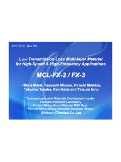
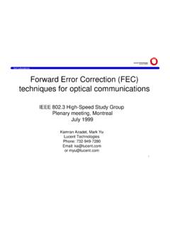
6 If the preceding bit is 1, then 10 maps to +1if the preceding bit is 0, then 00 maps to -1last two bits of each row form the pam4 block termination symbol FEC frame 064 bits FEC frame 1 FEC frame 2 FEC frame 3 FEC frame 4termination bits8687161717 IEEE , January 2012, Newport BeachPMA Frame Overhead Bits Each PMA per-lane frame has 4 overhead bits. Must be randomized or at least friendly . Various applications .. PMA frame alignment (see previous slide) lane identification control channel for remote transmitter control vendor specific use18 IEEE , January 2012, Newport BeachPre-Coding 1/(1+D) modulus 4 pre-coding See bliss_01_0311, Signaling Terminology; PAM-M and Partial Response Precoders Rx uses a (1+D) mod 4 after slicing Simple to implement Very low Complexity; similar complexity to duo-binary precoder. Pre-coding is mandatory; negotiation is not required.+ pam4 : Modulo 4 TTxEqualizer & SlicerChannel+TPAM4: Mod 4 0-3_19 IEEE , January 2012, Newport ud Ra te GB/sCoding Gain@1E-15 BER (dB)RS on GF(210).
7 Block size 4440 bits pam4 with Precoding for burst errorsPAM4 Burst Error Coding gainRandom Error coding gainMotivation for pre-coding Mitigates error propagation in DFE and MLSD receivers. Greatly reduces number of errors per burst. For 1-tap DFE, reduces burst to two errors, one at beginning and one at end For MLSD see dabiri_01_0911 Enabling Improved DSP Based Receivers for 100g Backplane 19 Graph shows improved coding gain (blue) due to precoding. The delta between burst error and random error is ~ with 1/(1+D) mod 4 precodingimprovement due to pre-codingT = 16T = 4T = 820 IEEE , January 2012, Newport BeachPAM4 Block Termination pam4 block termination symbol every 32 pam4 symbols For efficiency, each pam4 termination symbol transmits one data bit. 63 data bits sent every 32 pam4 symbols Increases baud rate by 64/63. Each pam4 block termination symbol is mapped to either +1 or -1. At the transmitter, termination added within the precoder. At the detector, termination removed after the detector.
8 See dabiri_01_0112. pam4 block termination Encoding is mandatory; negotiation is not framerfrom FECmod4 Dindicates termination symbolFunctional representation of block termination and pre-codingPRE-CODERto output driver21 IEEE , January 2012, Newport BeachMotivation for pam4 Block Termination Block termination by transmitting known pam4 symbols on a regular cycle efficient and effective MLSD, maximum likelihood sequence detection (dabiri_01_0911) parallel DFE implementations KeshabK. Parhi, Pipelining of parallel multiplexor loop and Decision Feedback Equalizers, ICASSP, 200422 IEEE , January 2012, Newport BeachPAM4 Encoding Gray mapping pre-coder output {10, 11, 01, 00} maps to {+1,+1/3,-1/3,-1} based on 2B1Q coding used in HDSL and ISDN23 IEEE , January 2012, Newport BeachPMA synchonization Lock to pam4 termination blocks by searching for pam4 termination symbols pam4 termination symbols (1 in 32) are always either +1 or -1. Similar to framing on 10 or 01 sequence for 64B/66B, can borrow and modify 64B/66B synchronization state machine.
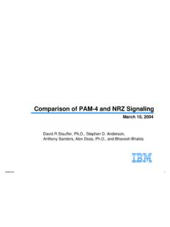
9 Lock to PMA frame Use known content of overhead bits. Once locked to the pam4 termination blocks, look for 4 bits (2 pam4 symbols) every 88 rows. Again, similar to 64B/66B , January 2012, Newport BeachEnergy Efficient Ethernet Operation Fast synchronization for REFRESH and WAKE. Synchronize on pam4 termination symbols. Use prescribed sequence to accelerate synchronization. For REFRESH, PCS and FEC not required. Replace with scrambled sequence. Similar to EEE/LPI for 10 GBASE-T. For WAKE, rapid alignment markers not required by the PHY transmitter and receiver. Will still be required at the PCS RX at the PCS end point. No significant impact to work being done in EEE consensus group. Compatible and complementary with PCS state machine in , January 2012, Newport BeachThanks!26 IEEE , January 2012, Newport BeachBACKUP SLIDES27 IEEE , January 2012, Newport BeachPower spectrum with pam4 block termination symbols The simulated spectrum above shows no spectral content due to block termination symbols.
10 Pattern is repeating structure (not content) of 32 pam4 31 random pam4 symbols in {-1,-1/3,+1/3,-1} * 3 1 random pam4 symbol in {-1, +1} * 328 IEEE , January 2012, Newport BeachPAM4 SNR Loss due to Over clockingFor FEC baud rate of , the SNR loss due to over clocking SNRdelta= ( GHz)/2 = 109-35-30-25-20-15-10-50 Frequency (Hz)Insertion Loss (dB)Extended KR insertion Loss29 IEEE , January 2012, Newport BeachPrecodingMotivation: pam4 DFE bursts DFE s are well known to multiply errors in the feedback loop A single error will become a burst error Consider pam4 1-tap DFE with tap coeff= 1 If previous decision is wrong, then there is 3/4 probability of making a successive error Probability of K consecutive errors = (3/4)k Lower 1stDFE tap between to 1 have similar burst length as tap coefficient of 1 Tap of 1: Tap of : Tap of : A single random error may consume multiple Reed Solomon words Burst error coding gain is lower than coding gain for random tap valueError Propagation Decay Rate Input BER: 1E-12 Input BER: 1E-630 IEEE , January 2012, Newport Beach1/(1+D) Precodingfor DFE burst errors The burst error length of the DFE error events for pam4 can be reduced by using precoding pam4 Txprecodinguses a 1/(1+D) mod 4 See bliss_01_0311, Signaling Terminology; PAM-M and Partial Response Precoders Rx uses a (1+D) mod 4 after slicing Simple to implement Very low Complexity.