Transcription of 100G CWDM4 Technical Spec
1 CWDM4 MSA Technical Specifications Rev Page 1 August 27, 2014 100g CWDM4 MSA Technical Specifications 2km Optical Specifications Participants Editor David Lewis, JDSU Comment Resolution Administrator Chris Cole, Finisar The following companies were members of the CWDM4 MSA at the release of this specification: Company Technical Contributors Avago John Petrilla Finisar Chris Cole, Jonathan King JDSU David Lewis Oclaro Kiyohisa Hiramoto Sumitomo Electric Eddie Tsumura Contacts: Revisions Rev Date Description August 27, 2014 Initial Release CWDM4 MSA Technical Specifications Rev Page 2 August 27, 2014 CONTENTS CONTENTS .. 2 TABLES .. 3 FIGURES .. 3 1 GENERAL .. 4 SCOPE .. 4 CWDM4 MODULE BLOCK DIAGRAM .. 4 FUNCTIONAL DESCRIPTION .. 5 HARDWARE SIGNALING PINS .. 5 MODULE MANAGEMENT INTERFACE .. 5 HIGH SPEED ELECTRICAL CHARACTERISTICS .. 5 FEC Requirements .. 5 MECHANICAL DIMENSIONS.
2 5 OPERATING ENVIRONMENT .. 5 POWER SUPPLIES AND POWER DISSIPATION .. 5 2 CWDM4 OPTICAL SPECIFICATIONS .. 6 WAVELENGTH-DIVISION-MULTIPLEXED LANE ASSIGNMENTS .. 6 OPTICAL SPECIFICATIONS .. 6 CWDM4 transmitter optical specifications .. 7 CWDM4 receive optical specifications .. 8 CWDM4 illustrative link power budget .. 9 3 DEFINITION OF OPTICAL PARAMETERS AND MEASUREMENT METHODS .. 10 Test patterns for optical parameters .. 10 Square wave pattern definition .. 10 Skew and Skew Variation .. 10 Wavelength .. 10 Average optical power .. 10 Optical Modulation Amplitude (OMA) .. 11 Transmitter and dispersion penalty (TDP) .. 11 Reference transmitter requirements .. 11 Channel requirements .. 11 Reference receiver requirements .. 12 CWDM4 MSA Technical Specifications Rev Page 3 August 27, 2014 Test procedure .. 12 Extinction ratio .. 12 Transmitter optical waveform (transmit eye) .. 12 Receiver sensitivity.
3 12 Stressed receiver sensitivity .. 13 4 FIBER OPTIC CABLING MODEL .. 14 5 CHARACTERISTICS OF THE FIBER OPTIC CABLING (CHANNEL) .. 15 Optical fiber cable .. 15 Optical fiber connection .. 15 Connection insertion 15 Maximum discrete reflectance .. 15 Medium Dependent Interface (MDI) requirements .. 15 TABLES Table 2-1: Wavelength-division-multiplexed lane assignments .. 6 Table 2-2: CWDM4 operating range .. 6 Table 2-3: CWDM4 transmit characteristics .. 7 Table 2-4: CWDM4 receive characteristics .. 8 Table 2-5: CWDM4 illustrative power budget .. 9 Table 3-1: Patterns for optical parameter testing .. 10 Table 3-2: Transmitter compliance channel specifications .. 11 Table 4-1: Fiber optic cabling (channel) characteristics .. 14 Table 5-1: Optical fiber and cable 15 FIGURES Figure 1-1: Block diagram for CWDM4 transmit/receive paths .. 4 Figure 3-1 Test setup for measurement of receiver sensitivity .. 13 Figure 4-1: Fiber optic cabling model.
4 14 CWDM4 MSA Technical Specifications Rev Page 4 August 27, 2014 1 GENERAL SCOPE This Multi-Source Agreement (MSA) defines 4 x 25 Gbps Coarse Wavelength Division Multiplex (CWDM) optical interfaces for 100 Gbit/s optical transceivers for Ethernet applications including 100 GbE. Forward error correction (FEC) is required to be implemented by the host in order to ensure reliable system operation. Two transceivers communicate over single mode fibers (SMF) of length from 2 meters to at least 2 kilometers. The transceiver electrical interface is not specified by this MSA but can have, for example, four lanes in each direction with a nominal signaling rate of Gbps per lane. Different form factors for the transceivers are possible. Initial implementations are expected to use either the CFP4 or the QSFP28 module form factors. Other form factors are possible and are not precluded by this MSA.
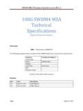
5 CWDM4 MODULE BLOCK DIAGRAM TP2 CWDM4 ModuleRetimerOpticaltransmitterRetimerOp ticaltransmitterRetimerOpticaltransmitte rRetimerOpticaltransmitterRetimerOptical receiverRetimerOpticalreceiverRetimerOpt icalreceiverRetimerOpticalreceiverWDdemu xWDmuxTP3TP4<0:3>TP1<0:3> CWDM4 ModuleRetimerOpticaltransmitterRetimerOp ticaltransmitterRetimerOpticaltransmitte rRetimerOpticaltransmitterRetimerOptical receiverRetimerOpticalreceiverRetimerOpt icalreceiverRetimerOpticalreceiverWDdemu xWDmuxTP3TP4<0:3>TP1<0:3>TP2 Patch cordOptical fiber cablePatch cordOptical fiber cableTX3TX2TX1TX0RX3RX2RX1RX0TX0TX1TX2TX 3RX0RX1RX2RX3 WD = Wavelength division NOTE Specification of the retime function is beyond the scope of this MSA. Figure 1-1: Block diagram for CWDM4 transmit/receive paths CWDM4 MSA Technical Specifications Rev Page 5 August 27, 2014 FUNCTIONAL DESCRIPTION CWDM4 modules comply with the requirements of this document and have the following common features: four optical transmitters; four optical receivers with signal detect; wavelength division multiplexer and demultiplexer; and a duplex optical connector for single-mode fiber.
6 The optical connector type is vendor specific but can include SC or LC types. HARDWARE SIGNALING PINS Hardware signaling pins are specified in the respective module form factor MSAs. MODULE MANAGEMENT INTERFACE The contents of the various ID registers shall comply with the requirements of the module MSA and the respective standards. In the case of QSFP28 modules, the management interface complies with SFF-8636. For CFP4 modules, the management interface complies with the CFP MSA Management Interface Specification. HIGH SPEED ELECTRICAL CHARACTERISTICS The detailed high speed electrical characteristics are not defined by this MSA. 100GE modules could be implemented in compliance with IEEE Annex 83E, CAUI-4 chip-to-module, or OIF CEI-28G-VSR or other interfaces to be defined. FEC REQUIREMENTS The optical link is specified to operate at a bit error ratio (BER) of 5 x 10⁻⁵. The host system is required to enable RS(528,514) FEC in accordance with clause 91 of IEEE-StdTM in order to comply with the IEEE 100g Mean Time to False Packet Acceptance (MTTFPA) requirements.
7 The option to bypass the Clause 91 RS-FEC correction function is not supported. MECHANICAL DIMENSIONS Mechanical dimensions are defined in the module form factor MSA specifications. QSFP28 is defined in SFF-8661. CFP4 is defined in the CFP4 Hardware Specification. OPERATING ENVIRONMENT All specified minimum and maximum parameter values shall be met when the host system maintains the operating case temperature and supply voltages within the module vendor specified operating ranges. All minimum and maximum limits apply over the operating life of the system. POWER SUPPLIES AND POWER DISSIPATION Module vendors shall specify the module power supply requirements in accordance with the module MSA. CWDM4 MSA Technical Specifications Rev Page 6 August 27, 2014 2 CWDM4 OPTICAL SPECIFICATIONS WAVELENGTH-DIVISION-MULTIPLEXED LANE ASSIGNMENTS The wavelength range for each lane of the CWDM PMD is defined in Table 2-1.
8 The center wavelengths are spaced at 20 nm. Table 2-1: Wavelength-division-multiplexed lane assignments Lane Center wavelength Wavelength range Module electrical lane L0 1271 nm to nm Tx0, Rx0 L1 1291 nm to nm Tx1, Rx1 L2 1311 nm to nm Tx2, Rx2 L3 1331 nm to nm Tx3, Rx3 OPTICAL SPECIFICATIONS The operating range for a CWDM4 PMD is defined in Table 2-2. A CWDM4 compliant PMD operates on single-mode fibers according to the specifications defined in Table 4-1 and characteristics in A PMD that exceeds the required operating range while meeting all other optical specifications is considered compliant ( , operating at km meets the operating range requirement of 2 m to 2 km). Table 2-2: CWDM4 operating range PMD type Required operating range 100GE- CWDM4 2 m to 2 km CWDM4 MSA Technical Specifications Rev Page 7 August 27, 2014 CWDM4 transmitter optical specifications The CWDM4 transmitter shall meet the specifications defined in Table 2-3.
9 Table 2-3: CWDM4 transmit characteristics Description Value Unit Signaling rate, each lane (range) 100GE 100 ppm GBd Line wavelengths (range) to nm to to to Side-mode suppression ratio (SMSR), (min) 30 dB Total average launch power (max) dBm Average launch power, each lane (max) dBm Average launch power, each lanea (min) dBm Optical Modulation Amplitude (OMA), each lane (max) dBm Optical Modulation Amplitude (OMA), each lane (min)b dBm Launch power in OMA minus TDP, each lane (min) dBm Transmitter and dispersion penalty (TDP), each lane (max)d dB Average launch power of OFF transmitter, each lane (max) -30 dBm Extinction ratio (min) dB Optical return loss tolerance (max) 20 dB Transmitter reflectancec (max) -12 dB Transmitter eye mask definition {X1, X2, X3, Y1, Y2, Y3} { , , , , , } aAverage launch power, each lane (min) is informative and not the principal indicator of signal strength.
10 A transmitter with launch power below this value cannot be compliant; however, a value above this does not ensure compliance. bEven if the TDP < , the OMA (min) must exceed this value. cTransmitter reflectance is defined looking into the transmitter. dTDP does not include a penalty for multi-path interference (MPI). CWDM4 MSA Technical Specifications Rev Page 8 August 27, 2014 CWDM4 receive optical specifications The CWDM4 receiver shall meet the specifications defined in Table 2-4. Table 2-4: CWDM4 receive characteristics Description Value Unit Signaling rate, each lane (range) 100GE 100 ppm GBd Line wavelengths (range) to nm to to to Damage threshold, each lane (min)a dBm Average receive power, each lane (max) dBm Average receive power, each laneb (min) dBm Receive power, each lane (OMA) (max) dBm Receiver reflectance (max) -26 dB Receiver sensitivity (OMA), each lane (max) at 5 x 10⁻⁵ BERc dBm Stressed receiver sensitivity (OMA), each laned (max) dBm Conditions of stressed receiver sensitivity test.