Transcription of 11.11 Storm Drains 11.11.1 Introduction - Connecticut
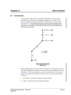
1 Storm Drainage Systems Storm Drains Introduction After the preliminary locations of inlets, connecting pipes and outfalls with tailwaters have been determined, the next logical step is the computation of the rate of discharge to be carried by each reach of the Storm drain, and the determination of the size and gradient of pipe required to convey this discharge. This is done by starting at the upstream reach, calculating the discharge and sizing the pipe, then proceeding downstream, reach by reach to the point where the Storm drain connects with other Drains or the outfall.
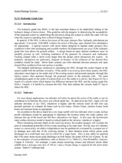
2 For manholes where the pipe size is increased, the downstream crown should be lower than the upstream crown by the amount of the energy loss in the manhole. The rate of discharge at any point in the Storm drain is not necessarily the sum of the inlet flow rates of all inlets above that section of Storm drain. It is generally less than this total. The time of concentration is most influential and as the time of concentration grows larger, the rainfall intensity to be used in the design grows smaller.
3 In some cases, where a relatively large drainage area with a short time of concentration is added to the system, the peak flow may be larger using the shorter time even though the entire drainage area is not contributing. The prudent designer will be alert for unusual conditions and determine which time of concentration controls for each pipe segment. See Section for a discussion on time of concentration. For ordinary conditions, Storm Drains should be sized on the assumption that they will flow full or practically full under the design discharge but will not flow under pressure head.
4 The Manning's formula is recommended for capacity calculations. In locations such as depressed roadway sections and underpasses where ponded water can be removed only through the Storm drain system, a higher design frequency should be analyzed to ensure the roadway stays open to traffic (see Table 11-2 for design criteria). The main Storm drain downstream of the depressed section should be designed by computing the hydraulic grade line and keeping the water surface elevations below the grates and/or established critical elevations for the check Storm .
5 General Guidelines The following items must be considered during the design of a Storm drain system. Storm Drains shall be designed for "just-full" condition. The head waters in structures shall be limited to meters (1 ft) below the top of grate, taking into consideration the possible effect of headwater in the next downstream structure. Underdrain pipes of 100 and 150 mm (4 in and 6 in) size should be laid in straight segments or gradual curves if possible. Where bends of underdrain are necessary to enter a structure they should be no greater than 30 degrees.
6 Long skew crossings of Storm drain laterals under pavement should be avoided. All roadway drainage, including the side and slope ditches shall be carried to a suitable outlet, preferably an existing stream. Where outletting to an existing stream is impractical, or where no stream is available, appropriate drainage rights must be obtained. The discharge of effluent from sanitary sewers, cesspools, septic tanks, discharge of cooling water or industrial wastes into a State maintained roadway drainage system will not be permitted.
7 Private connections to State drainage systems are only allowed after issuance of an encroachment permit accompanied by a special connection agreement. December 2003 ConnDOT Drainage Manual Storm Drainage Systems Roadway drainage shall not be outletted into existing drainage systems which are privately owned or those maintained by towns or cities except in the case where an independent outlet is not feasible due to excessive cost or other reasons. Where outletting into such a system, an agreement must be entered into with the municipality.
8 A deeded right to drain must be secured from owners of private systems. All existing metal pipes to be abandoned under the travelway are to be removed. Concrete pipes to be abandoned should be plugged at the ends. State drainage systems shall not be outletted into municipal systems which carry both Storm water and sanitary sewage, nor will any such municipal system carrying both Storm water and sanitary sewage be outletted into State systems. Diversion of watershed area should be avoided if possible.
9 However, in all cases where drainage is diverted from one watershed area to another, as is frequently the case in incised highways, the designer shall note the diversions in the computations and on the preliminary plans to better allow the reviewers and right of way negotiators to make proper provisions for the lawful disposal of the drainage from this area at the outlet locations. Utility conflicts may require design changes. New installations should be kept at least meters (1 ft) from any utilities.
10 The pertinent plans and computations for drainage systems on a project which originate or terminate on an adjacent project shall be furnished for review by the designer of the project being reviewed. The area used for runoff computation shall be shown on topographical maps also to be supplied. Each outlet must be carefully designed with erosion protection as needed and carried down steep slopes to lesser slopes where outlet erosion will not occur. Riprap shall be designed at all outlets not flowing over exposed rock or into deep watercourses or ponds.