Transcription of 115 - Food and Agriculture Organization
1 115. Chapter 7. Structural design Introduction thrust, shear, bending moments and twisting moments), Structural design is the methodical investigation of the as well as stress intensities, strain, deflection and stability, strength and rigidity of structures. The basic reactions produced by loads, changes in temperature, objective in structural analysis and design is to produce shrinkage, creep and other design conditions. Finally a structure capable of resisting all applied loads without comes the proportioning and selection of materials for failure during its intended life. The primary purpose the members and connections to respond adequately to of a structure is to transmit or support loads. If the the effects produced by the design conditions. structure is improperly designed or fabricated, or if the The criteria used to judge whether particular actual applied loads exceed the design specifications, proportions will result in the desired behavior reflect the device will probably fail to perform its intended accumulated knowledge based on field and model tests, function, with possible serious consequences.
2 A well- and practical experience. Intuition and judgment are engineered structure greatly minimizes the possibility also important to this process. of costly failures. The traditional basis of design called elastic design is based on allowable stress intensities which are chosen Structural design process in accordance with the concept that stress or strain A structural design project may be divided into three corresponds to the yield point of the material and should phases, planning, design and construction. not be exceeded at the most highly stressed points of Planning: This phase involves consideration of the the structure, the selection of failure due to fatigue, various requirements and factors affecting the general buckling or brittle fracture or by consideration of the layout and dimensions of the structure and results in permissible deflection of the structure. The allowable the choice of one or perhaps several alternative types stress method has the important disadvantage in that of structure, which offer the best general solution.
3 The it does not provide a uniform overload capacity for all primary consideration is the function of the structure. parts and all types of structures. Secondary considerations such as aesthetics, sociology, The newer approach of design is called the strength law, economics and the environment may also be design in reinforced concrete literature and plastic design taken into account. In addition there are structural and in steel- design literature. The anticipated service loading constructional requirements and limitations, which is first multiplied by a suitable load factor, the magnitude may affect the type of structure to be designed. of which depends upon uncertainty of the loading, the design : This phase involves a detailed consideration possibility of it changing during the life of the structure of the alternative solutions defined in the planning phase and for a combination of loadings, the likelihood, and results in the determination of the most suitable frequency, and duration of the particular combination.
4 In proportions, dimensions and details of the structural this approach for reinforced-concrete design , theoretical elements and connections for constructing each capacity of a structural element is reduced by a capacity- alternative structural arrangement being considered. reduction factor to provide for small adverse variations Construction: This phase involves mobilization of in material strengths, workmanship and dimensions. personnel; procurement of materials and equipment, The structure is then proportioned so that depending including their transportation to the site, and actual on the governing conditions, the increased load cause on-site erection. During this phase, some redesign fatigue or buckling or a brittle-facture or just produce may be required if unforeseen difficulties occur, such yielding at one internal section or sections or cause as unavailability of specified materials or foundation elastic-plastic displacement of the structure or cause the problems. entire structure to be on the point of collapse.
5 Philosophy of designing design aids The structural design of any structure first involves The design of any structure requires many detailed establishing the loading and other design conditions, computations. Some of these are of a routine nature. which must be supported by the structure and therefore An example is the computation of allowable bending must be considered in its design . This is followed by the moments for standard sized, species and grades of analysis and computation of internal gross forces, ( dimension timber. The rapid development of the 116 Rural structures in the tropics: design and development computer in the last decade has resulted in rapid adoption of Computer Structural design Software that has now replaced the manual computation. This has greatly reduced the complexity of the analysis and T1 T2 h1. design process as well as reducing the amount of time required to finish a project. 60 Standard construction and assembly methods have A evolved through experience and need for uniformity in the construction industry.)
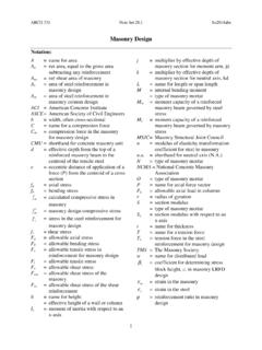
6 These have resulted in standard details and standard components for building if P=100N. construction published in handbooks or guides. P. T1=T2=58. design codes Many countries have their own structural design codes, T2 codes of practice or technical documents which perform a similar function. It is necessary for a designer to become familiar with local requirements or recommendations in regard to correct practice. In this chapter some examples are given, occasionally in a simplified form, in order to demonstrate procedures. They should not be assumed T1 to apply to all areas or situations. design of members in direct tension and compression P Tensile systems Tensile systems allow maximum use of the material FORCE DIAGRAM FOR POINT A because every fibre of the cross-section can be extended to resist the applied loads up to any allowable stress . As with other structural systems, tensile systems require depth to transfer loads economically across a span. As the sag (h) decreases, the tensions in the cable (T1 and T2) increase.
7 Further decreases in the sag would again increase the magnitudes of T1 and T2. h2 until the ultimate condition, an infinite force, would be T1 T2 required to transfer a vertical load across a cable that is 120 . horizontal (obviously an impossibility). A A distinguishing feature of tensile systems is that vertical loads produce both vertical and horizontal reactions. As cables cannot resist bending or shear, they transfer all loads in tension along their lengths. P The connection of a cable to its supports acts as a pin joint (hinge), with the result that the reaction (R) must be exactly equal and opposite to the tension in the cable (T). The R can be resolved into the vertical and horizontal directions producing the forces V and H. The horizontal reaction (H) is known as the thrust. The values of the components of the reactions can be obtained by using the conditions of static equilibrium if P=100N. and resolving the cable tensions into vertical and then horizontal components at the support points.
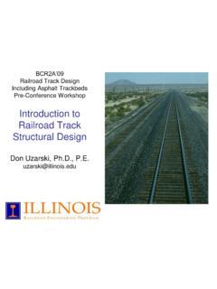
8 T1=T2=100N. Example Two identical ropes support a load P of 5 kN, as shown in the figure. Calculate the required diameter of the rope, if its ultimate strength is 30 MPa and a safety factor of is applied. Also determine the horizontal FORCE DIAGRAM FOR POINT A support reaction at B. Chapter 7 Structural design 117. 60 At support B, the reaction is composed of two components: 30 B. Bv = T2 sin 30 = sin 30 = kN. A BH = T2 cos 30 = cos 30 = kN. Short columns A column which is short ( the height is small P=5kN. compared with the cross-section area) is likely to fail because of crushing of the material. Note, however, that slender columns, which are tall T1 T2. compared with the cross-section area, are more likely to fail from buckling under a load much smaller than that needed to cause failure from crushing. Buckling is dealt with later. P. Free body diagram T= kN. Short columns 5 kN. T2= kN. The allowable stress in the rope is 30. = N/mm 30. 2. = MPa 4 = N/mm2 = MPa 30 4. = N/mm2 = MPa 4.
9 Force stress = Force Area stress =. ForceArea Slender columns stress =. Area Therefore: Example 103 A square concrete column, which is m high, is made Area required = 573 10. = mm 3. 2. Area required = = 573 mm2 of a nominal concrete mix of 1:2:4, with a permissible 3. Area required = d2 = 573 mm2 direct compression stress of MPa (N / mm ). What A = r2 = 4 is the required cross-section area if the column is d 2. A = r2 = required to carry an axial load of 300 kN? 4. F 300 000 N. Thus: A= = = 56 604 mm2. N/mm2. 4 573. d= = 27 mm (min). 4 573 the column should be minimum 238 mm square. d= = 27 mm (min).. 118 Rural structures in the tropics: design and development design of simple beams Bending stresses C C. When a sponge is put across two supports and gently pressed downwards between the supports, the pores N A. h at the top will close, indicating compression, and the pores at the bottom will open wider, indicating tension. T T. Similarly, a beam of any elastic material, such as wood or steel, will produce a change in shape when external loads are acting on it.
10 The moment caused by the external loads acting on the beam will be resisted by the moment of this internal couple. Therefore: M = MR = C (or T) h where: M = the external moment MR = the internal resisting moment C = resultant of all compressive forces on the cross- section of the beam T = resultant of all tensile forces on the cross-section of the beam h = lever arm of the reaction couple Now consider a small element with the area (R) at a distance (a) from the neutral axis (NA). Compression fc Tension fa ymax a N A. Figure Bending effects on beams The stresses will vary from maximum compression ft at the top to maximum tension at the bottom. Where the stress changes from compressive to tensile, there will be one layer that remains unstressed and this is called the neutral layer or the neutral axis (NA). Note that it is common practice to use the symbol f This is why beams with an I-section are so effective. for bending stress , rather than the more general symbol. The main part of the material is concentrated in Maximum compressive stress (fc) is assumed to occur in the flanges, away from the neutral axis.