Transcription of 12-Channel, 16-Bit, Enhanced Spec, PWM, RGB LED …
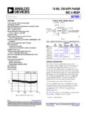
1 GNDVREGIREFSDTISCKIVCCOUTR0 OUTG0 OUTG3 OUTB3 SDTOSCKO1 FmVCCGNDP owerSupply(6 V to 17 V)DATACLKGNDC ontroller(1) GNDVREGIREFSDTISCKIVCCOUTR0 OUTG0 OUTG3 OUTB3 SDTOSCKO1 Fm OptionalDeviceDeviceOptionalProductFolde rSample &BuyTechnicalDocumentsTools &SoftwareSupport &CommunityTLC5971 SBVS146D AUGUST2010 REVISEDDECEMBER2015 TLC597112- channel , 16-Bit, EnhancedSpectru m,PWM, RGB, LED DriverWith Features2 ApplicationsRGBLEDC lusterLampDisplays1 12 Constant-CurrentSinkOutputChannels CurrentCapability:60 mA Per Channel3 Description Grayscale(GS)ControlWithEnhancedSpectrum TheTLC5971deviceis a 12-Channel, constant- (65536 Steps)individuallyadjustablecurrentswith 65536 PWM GlobalBrightnessControl(BC):grayscale(GS ) ,eachcolorgroupcan be7-Bit(128 Steps)for EachColorGroupcontrolledby 128 constant-currentsink stepswith theglobalbrightnesscontrol(BC) control Power-SupplyVoltageRange:andBC are accessiblethrougha two-wiresignal InternalLinearRegulator:6 V to 17 each DirectPowerSupply:3 V to Vchannelis set by a turnedoff whenthe IC is LEDS upplyVoltage:Up to 17 Vin an overtemperaturecondition.
2 Constant-CurrentAccuracy: channel -to- channel = 1% (Typical)DeviceInformation(1) Device-to-Device= 1% (Typical)PARTNUMBERPACKAGEBODYSIZE(NOM) DataTransferRate:20 MHzHTSSOP(20) (24) V AutoDisplayRepeatFunction(1) For all availablepackages,see the orderableaddendumatthe end of the datasheet. DisplayTimingResetFunction Internaland ExternalSelectableGS Clock ThermalShutdown(TSD)WithAutoRestart UnlimitedDeviceCascading OperatingTemperatureRange: 40 C to +85 CTypicalApplicationCircuitExample(Intern alLinearRegulatorUsingVCC= 6 V to 17 V)(1)The outputvoltagerangeis from0 V to :The numberof LEDsin serieschanges,dependingon the IMPORTANTNOTICEat the end of this datasheetaddressesavailability,warranty, changes,use in safety-criticalapplications,intellectual propertymattersand AUGUST2010 Applicationand Pin Configurationand Deviceand EquivalentInputand Mechanical,Packaging,and Orderable8 RevisionHistoryNOTE.
3 Pagenumbersfor previousrevisionsmay differfrompagenumbersin the (September2012)to RevisionDPage AddedPin Configurationand Functionssection,ESDR atings table,FeatureDescriptionsection,DeviceFu nctionalModes,Applicationand Implementationsection,PowerSupplyRecomme ndationssection,Layoutsection,Deviceand DocumentationSupportsection,andMechanica l,Packaging,and (June2012)to RevisionCPage Changedtypicalapplicationcircuit(interna llinearregulator), Changedtypicalapplicationcircuit(directp ower), Addedtypicalapplicationcircuitexample(di rectpowersupplyingVCC= 3 V to V, VLED= 15 V), 31 ChangesfromRevisionA (December2010)to RevisionBPage ChangedIOLKG parametertest Changedbit 217 descriptionin (August2010)to RevisionAPage Changedtypicalapplicationcircuit(interna llinearregulator).
4 1 Updatedbit namesfor BCR,BCG,and BCBin Changedtypicalapplicationcircuit(directp ower)..312 SubmitDocumentationFeedbackCopyright 2010 2015,TexasInstrumentsIncorporatedProduct FolderLinks:TLC5971 IREFGNDOUTR0 OUTG0 OUTB0 OUTR1 OUTG1 OUTB1 SDTISCKIVREGVCCOUTB3 OUTG3 OUTR3 OUTB2 OUTG2 OUTR2 SDTOSCKO1234567891020191817161514131211 PowerPAD(Bottom Side)SDTISCKINC(1)NCSCKOSDTOGNDNCIREFVRE GNCVCC123456181716151413 Thermal Pad(Bottom Side) AUGUST2010 REVISEDDECEMBER20155 Pin Configurationand FunctionsPWPP ackageRGEP ackage20-PinHTSSOP24-PinVQFNB ottomViewBottomViewNC = not connectedPin FunctionsPINI/ODESCRIPTIONNAMEPWPRGESDTI 91 ISerialdatainputfor the 224-bitshift registerSerialdatashift SDTIare shiftedto the LSB of the 224-bitshift registerwith the SCKI risingedgeSCKI102 IDatain the shift registerare shiftedtowardthe MSBat MSBdataof the shift registerappearon the 224-bitshift connectedto the MSBof the 224-bitshift clockedout at the inputshift clocksignalfromSCKIis adjustedto the timingof the serialdataoutputfor SDTOand the signalis
5 Thenoutputat decouplingcapacitorof 1 F mustbe outputcan be usedfor externaldevicesVREG2015I/Oas a terminalcan be connectedwith the VREG terminalof otherdevicesto increasethe ,this pin can be suppliedwith 3 V to V fromanexternalpowersupplyby connectingit to resistorconnectedbetweenIREFand GNDsets the maximumcurrentfor everyconstant-IREF116 terminalis directlyconnectedto GND,all outputsare forcedoff. Theexternalresistorshouldbe placedcloseto the be configuredin parallelto increasethe be appliedto be configuredin parallelto increasethe be appliedto be configuredin parallelto increasethe be appliedto Power-supplyterminalCopyright 2010 2015,TexasInstrumentsIncorporatedSubmitD ocumentationFeedback3 ProductFolderLinks:TLC5971 TLC5971 SBVS146D AUGUST2010 Functions(continued)PINI/ODESCRIPTIONNAM EPWPRGEGND,PowerPAD2 (PWP)PowergroundterminalGND,exposed 18 thermalpad (RGE)3, 4, 14,NC No internalconnection176 ,unlessotherwisenoted.
6 (1)(2)MINMAXUNITS upplyvoltage,VCC + ,SCKI + OUTR3,OUTG0to OUTG3,OUTB0to OUTB3 ,SCKO + OUTR3,OUTG0to OUTG3,OUTB0to OUTB375mAOutputcurrent(DC)VREG 30mAOperatingjunctiontemperature,TJ (max)150 CStoragetemperature,Tstg 55150 C(1)StressesbeyondthoselistedunderAbsolu teMaximumRatingsmay causepermanentdamageto the stressratingsonly,and functionaloperationof the deviceat theseor any otherconditionsbeyondthoseindicatedunder RecommendedOperatingConditionsis not absolute-maximum-ratedconditionsfor extendedperiodsmay affectdevicereliability.(2)All voltagevaluesare with respectto (HBM),per ANSI/ESDA/JEDECJS-001(1) 4000 ElectrostaticV(ESD)VdischargeCharged-dev icemodel(CDM),per JEDEC specificationJESD22-C101(2) 2000(1)JEDEC documentJEP155statesthat 500-VHBM allowssafe manufacturingwith a standardESDcontrolprocess.
7 (2)JEDEC documentJEP157statesthat 250-VCDM allowssafe manufacturingwith a TA= 40 C to +85 C, and VCC= 6 V to 17 V or VCC= VREG= 3 V to V, CHARACTERISTICSVCCS upplyvoltage,internalvoltageregulatoruse d617 VVREGS upplyvoltage,VREG connectedto outputVO17V(OUTR0to OUTR3,OUTG0to OUTG3,OUTB0to OUTB3)VIHHigh-levelinputvoltage(SDTI,SCK I) VREGVREGVVILLow-levelinputvoltage(SDTI,S CKI) VREGVVIHYSI nputvoltagehysteresis(SDTI,SCKI) VREGVIOHHigh-leveloutputcurrent(SDTO) 2mAIOLLow-leveloutputcurrent(SDTO)2mACon stantoutputsink currentIOLC60mA(OUTR0to OUTR3,OUTG0to OUTG3,OUTB0to OUTB3)4 SubmitDocumentationFeedbackCopyright 2010 2015, AUGUST2010 REVISEDDECEMBER2015 RecommendedOperatingConditions(continued )at TA= 40 C to +85 C, and VCC= 6 V to 17 V or VCC= VREG= 3 V to V, (VREG) 25mATAO peratingfree temperaturerange 4085 CTJO peratingjunctiontemperature 40125 CAC CHARACTERISTICSfCLK(SCKI)Dataclockfreque ncyand GS controlclockfrequency, ,SCKI10nstSUSetuptime,SDTI SCKI 5nstHHoldtime,SDTI SCKI (1)PWP(HTSSOP)RGE(VQFN)UNIT20 PINS24 PINS C/W JCtopJunction-to-case(top) C/W C/W C/W C/W JCbotJunction-to-case(bottom) C/W(1)
8 For moreinformationabouttraditionaland new thermalmetrics,see theSemiconductorand IC PackageThermalMetricsapplicationreport, TA= 40 C to +85 C, VCC= 6 V to 17 V or VCC= VREG= 3 V to V, VLED= 5 V, and CVREG= 1 F, at TA= 25 C and VCC= 12 ,SDTO/SCKOIOH= 2 mAVREG ,SDTO/SCKOIOL= 2 ,SDTI/SCKIVI= VREGor GND 11 ASDTI/SCKI= low, BLANK= 1, GSn= FFFFh,ICC24mABCX= 7Fh,VOUTXn= 1 V, RIREF= 24 k (IOLCMax= 2 mA)SDTI/SCKI= low, BLANK= 1, GSn= FFFFh,ICC169mABCX= 7Fh,VOUTXn= 1 V, RIREF= k (IOLCMax= 30 mA)SDTI= 10 MHz,SCKI= 20 MHz,BLANK= 0,SupplycurrentICC2autorepeatenable,exte rnalGS clockselected,GSn= FFFFh,1422mABCX= 7Fh,VOUTXn= 1 V, RIREF= k (IOLCMax= 30 mA)SDTI= 10 MHz,SCKI= 20 MHz,BLANK= 0,ICC3autorepeatenable,externalGS clockselected,GSn= FFFFh,2136mABCX= 7Fh,VOUTXn= 1 V, RIREF= (IOLCMax= 60 mA)All OUTXnon, BCX= 7Fh,VOUTXn= 1 V,IOLCC onstantoutputcurrent, 1 V, RIREF= (IOLCMax= 60 mA)All OUTX noff, BCX= 7Fh,VOUTXn= 17 V,IOLKGL eakageoutputcurrent, AVOUTfix= 17 V, RIREF= (IOLCMax= 60 mA)Copyright 2010 2015,TexasInstrumentsIncorporatedSubmitD ocumentationFeedback5 ProductFolderLinks.
9 TLC5971100(Iat VCC = 3 V)XnOLC(Iat VCC = V) (Iat VCC = 3 V) V 3 V-D(%/V) = I(mA) = 41 Xn(IDEAL) ( )WD(%) =Ideal Output Current-(Ideal Output Current)(I+ I+ I+ I)X0X1X2X3 OLCOLCOLCOLC4 100D(%) =-1 IXnOLC(I+ I+ I+ I)X0X1X3X2 OLCOLCOLCOLC4 100 TLC5971 SBVS146D AUGUST2010 (continued)At TA= 40 C to +85 C, VCC= 6 V to 17 V or VCC= VREG= 3 V to V, VLED= 5 V, and CVREG= 1 F, at TA= 25 C and VCC= 12 (1)All OUTXnon, BCX= 7Fh,VOUTXn= VOUTfix= 1 V, IOLC( channel -to-channelin samecolorgroup), 3% 1%3%RIREF= (IOLCMax= 60 mA)OUTXnConstantcurrenterror(2)All OUTXnon, BCX= 7Fh,VOUTXn= VOUTfix= 1V, IOLC1(device-to-devicein samecolorgroup),RIREF= (IOLCMax= 60 mA),at samegroupedcoloroutput 4% 14%OUTXnof OUTR0-3,OUTG0-3,and OUTB0-3 Line regulationof constant-currentoutput,All OUTnon, BCX= 7Fh,VOUTXn= VOUTfix= 1 V, IOLC2 1 (3)RIREF= (IOLCMax= 60 mA)(1)The deviationof eachoutputin the samecolorgroup(OUTR0-OUTR3or OUTG0-OUTG3or OUTB0-OUTB3)fromthe averagecurrentfromthe calculatedby Equation1:where(a) X = R/G/B,(b) n = 0-3.
10 (1)(2)The deviationof eachcolorgroupconstant-currentaveragefro mthe Equation2:where(a) X = R/G/B.(2)Idealcurrentis calculatedby Equation3 for the OUTR nand OUTG ngroups:where(a) X = R/G/B.(3)(3)Line regulationis calculatedby Equation4:where(a) X = R/G/B,(b) n = 0-3.(4)6 SubmitDocumentationFeedbackCopyright 2010 2015,TexasInstrumentsIncorporatedProduct FolderLinks:TLC59711003 V 1 V- (Iat V= 1 V)XnOU