Transcription of 1296 Loop Yagi Dimensions - NTMS
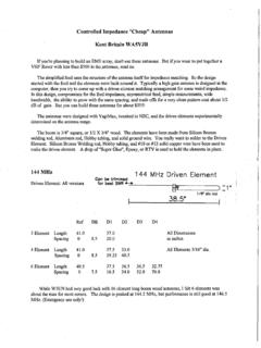
1 NTMS 12' (45 Element) And 6' (25 Element) 1296 MHzLoop yagi Club ProjectCoordinator:Ross Pounders, K5 ZSJD esign:Al Ward, W5 LUA (Oct 29, 1979)Documentation:Steve Gradijan, WB5 KIAM achine work:Wes Atchison, WA5 TKUThis is modified from a design by G3 JVL/W1JR. This yagi has six new directors with the diameter ofloop elements modified according to an article by G3 JVL to compensate for a 3/4" diameter boom,1/4" by " thick directors and reflectors; and a brass driven element 1/4" wide by ".Specifications:Boom diameter:3/4"Boom Length:either 12' or 6'Gain 6':17 dB iGain 12':20 dB iPattern: The 3 dB beamwidth is approximately 13 degrees with first side lobes down 12 and 14 dBNotes:1- Use a boom brace on 12' boom2- Height of the driven element will be about 1/2" less than the width for the bestVSWR. VSWR is less than :1 at Antenna Kit:Parts included:# 4 stainless steel screws, nuts, and lock washers for each element1 ea. brass strip for driven element1/4 aluminum strips about 10 in lengthhollow bolt for driven element supportUser provides:3/4 6' or 12' boomN coax connector to 14110 or so of 141 for driven element (threaded through hollow bolt)bracket for N coax connector to antenna boommast to boom bracketextra boom support for 12'Preparing the 1/4 Al strips:Figure 1.
2 Loop Strip ".25"The parts provided by NTMS include 1/4 .032 aluminum strips for the loops . The strips are long and have one of the holes for mounting the loops punched in one end. Figure 1 shows thecompleted strip ready for mounting. The strips are sharp and can be smoothed by hand sanding or aDremmel tool at slow speed with a rough drum sander tool (use eye protection). You should first checkthe measurements of the punched hole in one end to insure it is 1/4 center to edge of the strip and alsomake sure that the strip has not been mangled by the shear. Table 1 gives the proper lengths of thestrips. A 6 ft version will only use 22 DE (brass) Table 1. Strip Lengths for 12 ft boomBoom Element Positions:Table 2 gives the boom element positions for both 6' and 12' antennas. You may measure and drill youown boom using a #32 clearance drill bit for the #4 stainless steel screws or use a templet made for thepurpose of EMT conduit. The boom will slip inside the conduit.
3 See Ross Pounders (K5 ZSJ)for use of the templet. W5 LUA has a similar boom drilling fixture using 1 square aluminum also has a suitable boom (6' & 12')PositionininchesElementsCommon to 6'and 12' boomsElementNumber (12'only)Positionin inchesElements for12 ' boom 2. Boom Element SpacingsDriven ElementTotal length is "After a " diameter hole is drilled or punched at the end of the driven element, cut off the last 1/4"of the driven element so that what is left is a " radius half circle which can be soldered to the outerconductor of the .141 semirigid cable. Mount the driven element approximately 1/8" above the boomwith a spacer. The driven element slides over the semirigid cable and is bent into a circle where thecenter conductor of the cable will be soldered to the end of the element with the .070 diameter holeand the half circle is soldered to the semirigid outer jack just below where the center conductor issoldered. See picture below of my early prototype unit that has been on many grid expeditions!
4 Good luck and happy building! ".07".141" DiameterDrilled to fit centerconductor of .141"semirigid coax