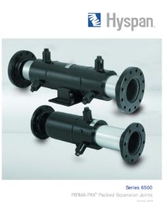
Transcription of 13736 Hyspan 3500 Brochure
1 Installation Procedure Application: Series 3500 Externally Pressurized Expansion Single expansion joints, types 3501 and 3502, are available Joints are designed for applications where the principal with an anchor base designed as a main anchor. Refer to motion is axial to the centerline of the expansion joint, and main anchor forces in the Anchor Forces section on page 5. the system includes guides, supports and anchors sufficient for force required. The anchor base height and base pattern to restrain the piping at the service and test conditions.
2 Steam for both configurations are given in Table 4, page 7. systems must include adequate traps to remove condensate. CAUTION: The structure attached to the anchor base must Liquid systems must include surge compensation. be capable of restraining the thrust forces and moments developed by the expansion joint. Operating Conditions: Series 3500 expansion joints are supplied with a tag attached stating the Part Number and Shipping Restraints: External restraints are installed at the Design Pressure. Standard designs are 150 psig and 300 psig, factory to insure installation at the correct length and and the test pressures are 225 psig and 450 psig respectively.
3 Alignment. They are painted yellow and labeled Shipping The design temperature for all standard joints is 500 F. Bars, Remove after Installation. Leave these restraints Be certain that the system conditions and test conditions installed until after the installation of the expansion joint is do not exceed the design values. complete but they must be removed prior to pressure testing. CAUTION: Shipping Bars are not designed to react Movement: The axial travel of the joint is included in the part the pressure thrust of the expansion joint they must be number as the last digit(s) P/N 3501-148-4 is designed removed prior to testing.
4 Normally the shipping restraints for 4" axial travel (compression). Consult the purchase are installed by welding remove by cutting and grinding specification to confirm the correct part number and location welds flush. in the system. Refer to Travel Required on Page 5 for the method of calculating pipe expansion or contraction. Standard expansion joints are factory set for the travel tabulated in this catalog. The principal travel is axial Flow Direction and Orientation: The flow direction can be compression (pipe expansion) with allowance for extension either direction for Series 3500 expansion joints.
5 Be certain if the pipe temperature is reduced below the installation that the free end is attached to the pipe that expands on temperature. Refer to the purchase specifications for joints single joints (3501AB & 3502AB) with an anchor base. The ordered with special settings. drain port must be at the bottom of the joint for horizontal and vertical installations. Post Installation Inspection Media & Environment: Series 3500 expansion joints are 1. Inspect the expansion joint for damage. designed for properly maintained steam, hot water and 2.
6 Are the Shipping Restraints removed? chilled water systems. They can be used for other media that 3. Is the joint free to move and is the pipe supported and are compatible with the materials of construction. Refer to guided to ensure that the pipe motion is axial to the Material Specifications on Page 7 for the materials used for expansion joint? standard construction. Be certain that the exterior of the 4. Is the expansion joint installed at the correct location expansion joint is not exposed to corrosive substances such and are the anchors, guides and supports installed in as minerals in ground water and road salt.
7 Accordance with the system design? 5. Are the guides and supports free to allow the movement Guides, Supports, Anchors: Series 3500 expansion joints of the expansion joint? are designed for applications where the principal movement 6. Is the supporting structure for the anchor adequate to is axial to the centerline of the expansion joint, and the system react the forces and moments? includes guides, supports and anchors. Refer to Applications on Pages 3 and 4 for system requirements. Refer to Hyspan Installation Preset Series 9500 Catalog 1004 for pipe guide design information.
8 Series 3500 expansion joints can be ordered from the factory Anchor Base: Type 3505 and 3506 dual expansion joints with factory preset; however, if it is necessary to change the include an intermediate anchor base to ensure that the travel during installation, the shipping bars must be removed bellows element on each side of the base absorbs the and the length adjusted. The following table is a tabulation of motion on one side. Refer to intermediate anchor forces in the thermal expansion or contraction for various pipe run the Anchor Forces section on Page 5 for force required.
9 Lengths corresponding to temperature differences from 70 F. Copyright 2004 Hyspan Precision Products, Inc. 14 Printed in the USA. For example, if the expansion joint is used as a replacement temperature is 170 F over a 200 foot run, the joint must be in a system that has not cooled down, and the pipe compressed ". Table 11 Installation Preset Temperature Distance Between Anchors Feet Difference F 50 100 150 200 250 300. 20 30 40 50 60 70 80 90 100 110 120 140 160 180 200 1 2 3 4 5 6 7. Field preset is not recommended unless it cannot be avoided.
10 Anticipated, Series 3500 expansion joints can be ordered Note that there must be a significant temperature difference with threaded adjusting rods factory installed to facilitate to warrant presetting during installation. If presetting is presetting. FIVE YEAR LIMITED WARRANTY. This warranty is given by Hyspan PRECISION PRODUCTS, INC. ( Hyspan ) for the benefit of the first purchasers for use of its Series 3500 Externally Pressurized Expansion Joints manufactured by Hyspan to standard catalog construction or standard construction with laminated Alloy 625 bellows.