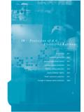
Transcription of 16 Transformer and Transformer-feeder Protection
1 Protection overcurrent earth fault of differential protectionduring magnetising inrush differential andrestricted earth fault Transformer and gas monitoring of of Transformer 16 Transformer andTransformer-feeder INTRODUCTIONThe development of modern power systems has beenreflected in the advances in Transformer design. This hasresulted in a wide range of transformers with sizesranging from a few kVA to several hundred MVA beingavailable for use in a wide variety of considerations for a Transformer Protection packagevary with the application and importance of thetransformer. To reduce the effects of thermal stress andelectrodynamic forces, it is advisable to ensure that theprotection package used minimises the time fordisconnection in the event of a fault occurring within thetransformer.
2 Small distribution transformers can beprotected satisfactorily, from both technical andeconomic considerations, by the use of fuses orovercurrent relays. This results in time-delayedprotection due to downstream co-ordinationrequirements. However, time-delayed fault clearance isunacceptable on larger power transformers used indistribution, transmission and generator applications,due to system operation/stability and cost ofrepair/length of outage faults are generally classified into and terminal and Transformer accessory load tap changer operating or uncleared external faultsFor faults originating in the Transformer itself, theapproximate proportion of faults due to each of thecauses listed above is shown in Figure 16 Transformer andTransformer-Feeder ProtectionNetworkProtection & Automation Guide 255 Winding and terminalCoreTankand accessoriesOLTCF igure.
3 Transformer fault WINDING FAULTSA fault on a Transformer winding is controlled inmagnitude by the following earthing leakage connectionSeveral distinct cases arise and are examined Star-Connected Winding withNeutral Point Earthed through an ImpedanceThe winding earth fault current depends on the earthingimpedance value and is also proportional to the distanceof the fault from the neutral point, since the faultvoltage will be directly proportional to this a fault on a Transformer secondary winding, thecorresponding primary current will depend on thetransformation ratio between the primary winding andthe short-circuited secondary turns. This also varies withthe position of the fault, so that the fault current in thetransformer primary winding is proportional to thesquare of the fraction of the winding that is short-circuited.
4 The effect is shown in Figure Faults inthe lower third of the winding produce very little currentin the primary winding, making fault detection byprimary current measurement Star-connected winding withNeutral Point Solidly EarthedThe fault current is controlled mainly by the leakagereactance of the winding, which varies in a complexmanner with the position of the fault. The variable faultpoint voltage is also an important factor, as in the caseof impedance earthing. For faults close to the neutralend of the winding, the reactance is very low, and resultsin the highest fault currents. The variation of currentwith fault position is shown in Figure secondary winding faults, the primary winding faultcurrent is determined by the variable transformationratio; as the secondary fault current magnitude stayshigh throughout the winding, the primary fault current islarge for most points along the Delta-connected WindingNo part of a delta-connected winding operates with avoltage to earth of less than 50% of the phase range of fault current magnitude is therefore lessthan for a star winding.
5 The actual value of fault currentwill still depend on the method of system earthing; itshould also be remembered that the impedance of adelta winding is particularly high to fault currentsflowing to a centrally placed fault on one leg. Theimpedance can be expected to be between 25% and50%, based on the Transformer rating, regardless of thenormal balanced through-current impedance. As theprefault voltage to earth at this point is half the normalphase voltage, the earth fault current may be no morethan the rated current, or even less than this value if thesource or system earthing impedance is appreciable. Thecurrent will flow to the fault from each side through thetwo half windings, and will be divided between two 16 Transformer and Transformer -Feeder ProtectionNetwork Protection & Automation Guide 256 52010040305060109080701002015 Current (per unit)Distance of fault from neutral (percentage of winding)Primary currentFault currentFigure Earth fault currentin solidly earthed star windingFigure Earth fault currentin resistance-earthed star winding202001010403050605030409080701006 0907080100p)Fault current (I (I (IF (IF)F)FFIFIpIpI(percentage of winding)Percentage of respective maximumsingle-phase earthfault currentphases of the system.)
6 The individual phase currents maytherefore be relatively low, resulting in difficulties inproviding Phase to Phase FaultsFaults between phases within a Transformer arerelatively rare; if such a fault does occur it will give riseto a substantial current comparable to the earth faultcurrents discussed in Section Interturn FaultsIn low voltage transformers , interturn insulationbreakdown is unlikely to occur unless the mechanicalforce on the winding due to external short circuits hascaused insulation degradation, or insulating oil (if used)has become contaminated by high voltage Transformer connected to an overheadtransmission system will be subjected to steep frontedimpulse voltages, arising from lightning strikes, faults andswitching operations.
7 A line surge, which may be ofseveral times the rated system voltage, will concentrate onthe end turns of the winding because of the highequivalent frequency of the surge front. Part-windingresonance, involving voltages up to 20 times rated voltagemay occur. The interturn insulation of the end turns isreinforced, but cannot be increased in proportion to theinsulation to earth, which is relatively great. Partialwinding flashover is therefore more likely. The subsequentprogress of the fault, if not detected in the earliest stage,may well destroy the evidence of the true short circuit of a few turns of the winding will give riseto a heavy fault current in the short-circuited loop, butthe terminal currents will be very small, because of thehigh ratio of transformation between the whole windingand the short-circuited graph in Figure shows the corresponding datafor a typical Transformer of impedance with theshort-circuited turns symmetrically located in the centreof the Core FaultsA conducting bridge across the laminated structures ofthe core can permit sufficient eddy-current to flow tocause serious overheating.
8 The bolts that clamp the coretogether are always insulated to avoid this trouble. Ifany portion of the core insulation becomes defective, theresultant heating may reach a magnitude sufficient todamage the additional core loss, although causing severe localheating, will not produce a noticeable change in inputcurrent and could not be detected by the normalelectrical Protection ; it is nevertheless highly desirablethat the condition should be detected before a majorfault has been created. In an oil-immersed Transformer ,core heating sufficient to cause winding insulationdamage will also cause breakdown of some of the oilwith an accompanying evolution of gas. This gas willescape to the conservator, and is used to operate amechanical relay; see Section Tank FaultsLoss of oil through tank leaks will ultimately produce adangerous condition, either because of a reduction inwinding insulation or because of overheating on loaddue to the loss of may also occur due to prolongedoverloading, blocked cooling ducts due to oil sludging orfailure of the forced cooling system, if Externally Applied ConditionsSources of abnormal stress in a Transformer system OverloadOverload causes increased 'copper loss' and a consequenttemperature rise.
9 Overloads can be carried for limitedperiods and recommendations for oil-immersedtransformers are given in IEC thermal time constant of naturally cooledtransformers lies between hours. Shorter timeconstants apply in the case of force-cooled transformers . 16 Transformer and Transformer -Feeder ProtectionNetwork Protection & Automation Guide 257 Figure Interturn fault current/numberof turns short-circuited2050101540202510080 Fault current (multiples of rated current)Turns short-circuited (percentage of winding)60 Primary current (multiples of rated current)246108 Primary inputcurrentFault current inFault current inshort circuited System faultsSystem short circuits produce a relatively intense rate ofheating of the feeding transformers , the copper lossincreasing in proportion to the square of the per unitfault current.
10 The typical duration of external shortcircuits that a Transformer can sustain without damageif the current is limited only by the self-reactance isshown in Table IEC 60076 provides furtherguidance on short-circuit withstand : Fault withstand levelsMaximum mechanical stress on windings occurs duringthe first cycle of the fault. Avoidance of damage is amatter of Transformer OvervoltagesOvervoltage conditions are of two surge frequency overvoltageTransient overvoltages arise from faults, switching, andlightning disturbances and are liable to cause interturnfaults, as described in Section These overvoltagesare usually limited by shunting the high voltageterminals to earth either with a plain rod gap or by surgediverters, which comprise a stack of short gaps in serieswith a non-linear resistor.