Transcription of 16 x 25 x 5mm Two Function Decoder - Bachmann Industries
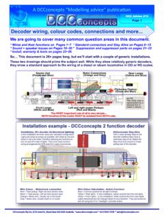
1 PlugMeaningWire Harness1 Motor terminal 1 Orange2 Function output B (rear headlight)Yellow4 Left rail pickupBlack5 Motor terminal 2 Gray6 Function output A (front headlight)White7 Function positive commonBlue8 Right rail pickupRedFeatures Adjustable starting voltage Acceleration and deceleration separately adjustable Directional lighting and dimming feature Programming on main track Advanced consisting Operation on standard DC railroads (analog operation)if desired. This feature can be StartedThe Bachmann E-Z COMMAND locomotive decoderscan be used with standard digital control systems with an NMRA conformance seal. If in doubt, ask thesystem the maximum current-carrying capacity of the outputs must not be exceeded. Exceeding this willdestroy the Decoder . The metal components of thedecoder must not touch the metal parts of the chassis or the body of the locomotive. This could cause a short-circuit within the locomotive Decoder which might destroy it.
2 Extreme care must be taken when operating locomotivesequipped with E-Z COMMAND decoders usingoverhead line (catenary), either on conventional DC orDCC layouts. Choose either catenary or track poweroperation (not both), or the locomotive could be subjectto double voltage that would destroy the installing an E-Z COMMAND Decoder , check theloco in normal DC operation to make sure that it worksas it should before modifying the locomotive. Replaceworn wheel contacts, motor brushes and bulbs asneeded. Only a locomotive that is mechanically fine willfunction properly with a locomotive decoders come with a NMRA/NEM652 mediumplug. To install this type Decoder simply remove thedummy socket in your locomotive and install thedecoder plug. To ensure the headlights work correctly,you must align the plug properly. Pin 1 of the plugconnects to the orange wire (Fig 1). Ensure this isaligned to Pin 1 of the locomotive. If the plug is installedbackwards the lights will not work.
3 When installing orremoving the plug, be careful that the pins do notbecome bent or broken. Note: Pin 1 is indicated byeither A1 or a colored dot install a Decoder with wire harness, refer to the wiringguide below for proper 1 Two Function DecoderWiring Guide For Decoder with 8-Pin Plug and Decoder with Wire Harness:NMRAFig. 1 Follow the E-Z COMMAND instructions to change thedecoder address. The Decoder will operate as suppliedbut also has advanced programmable functionsaccessible using suitable equipment. Do not worry if youdo not understand all of the functions of the advice, please call the Service Department at 1-800-356-3910 or e-mail via Youcan also visit for additional x 25 x 5mmBachmann Industries , East Erie AvenuePhiladelphia, PA 19124 the decoderPLEASE NOTE that except for allocating address anddirection, the standard E-Z COMMAND system is unable toprogram Decoder CVs. A more advanced system, such asBachmann s DyNAMis WirElEss DigitAl COMMANDCONtrOlis required to program Decoder locomotive address, acceleration and decelerationdelay, and all other features of the locomotive Decoder canbe changed as often as desired by reprogramming.
4 Thefeatures are "stored" permanently in special locations evenwhen the operational voltage is switched off. These locations are called "configuration variables" or simply configuration of the variables is done electronically,which means that it is not necessary to open the locomotiveagain after the Decoder has been installed. On delivery, the Decoder is programmed for operating withthe basic address 03, 28 speed steps and an internalspeedline. The Decoder can be used immediately on purchase with these basic configurations. All configurationscan, of course, be the installation on equipment other than Bachmann E-Z COMMAND .Place the locomotive on the programming track (without itshousing) and read the address. At the factory, the Decoder isprogrammed to the address 03. If you have connected thedecoder correctly thus far, you should now be able to read the address. If you are not able to do so, it is possible that you made a mistake when connecting the wires.
5 Do notsubject the loco to full-running track power until you obtain thecorrect "03" address read-out. Check the wire connections andchange them as required. You should now be able tosend your locomotive on its first test run on your of supported CVsBits are counted beginning with 1 CV Min-MaxCV DefinitionDeft1 1-99 Locomotive address32 0-31 Starting voltage103 1-255 Acceleration momentum14 1-255 Deceleration momentum17- Version number468- Manufacturer ID10117 Extended address, high byte018 Extended address, low byte019 1-99 Multi unit (consist) address0CV29 - Default value decimal 6 Decoder configuration byte 1 Bit No. 8 7 6 5 4 3 2 1 Default 0 0 0 0 0 1 1 0 Bit = 1-- Decoder uses extendedaddress CV s 17/18--Operation on digital andanalog28/128 speed stepsOperates with reversedirectionBit = 0-- Decoder uses CV1 valueas address--Digital operation only14/27 speed stepsOperates with normaldirectionCV50 - Default value decimal 4 Decoder configuration byte 2 Bit No.
6 8 7 6 5 4 3 2 1 Default 0 0 0 0 0 1 0 0 Bit = 1-----Slows with brake momentum(set in CV4) if DC on trackwhen CV29 is set for DCC only--Bit = 0-----Does not operate if DC on trackwhen CV29 is set for DCC only--CV51 - Default value 0 The bit set corresponds to the Function button F1 to F8 to switch output to thedimmed value (CV52). If set to 0 the output can be switched on/off with F0 Bit No. 8 7 6 5 4 3 2 1 Default 0 0 0 0 0 0 0 0 Bit = 1 Function output dimmed by F8 Function output dimmed by F7 Function output dimmed by F6 Function output dimmed by F5 Function output dimmed by F4 Function output dimmed by F3 Function output dimmed by F2 Function output dimmed by F1 Bit = 0--------52 0 - 255 Dimming F-output A, 0 is dark 255 is max brightness 64 Function output dimming0 Dark255 Maximum brightnessPrinted in ChinaTechnical DataNormal operation.
7 Current carrying capacityof the Decoder in sum1 Amotor output1 Afunction output 100 mAaddresses1 - 9999speed steps14, 27, 28, 128dimensions16 x 25 x 5mmReset to Factory SettingsYou can reset this Decoder to factorydefault settings by setting configurationvariable 8 (CV8) to a value of 8 using anyNMRA-compliant DCC