Transcription of 1747-IN063C-EN-P, Universal Serial Bus (USB) to DH-485 ...
1 Publication 1747-IN063C-EN-P - January 2006 Installation InstructionsUniversal Serial Bus (USB) to DH-485 Interface ConverterCatalog Number ..3 Computer and Operating System Requirements ..3 Install the Interface Converter ..3 Install the Ferrite Collar (European EMC Compliance) .. 4 Connect DH-485 Devices to the Interface Converter s RS-485 Port ..5 Connect DH-485 Devices to the Interface Converter s RS-232 Port ..6 Install the Drivers..7 Identify the Assigned COM Port .. 11 Configure the 1747-UIC Interface Converter in RSLinx.
2 11 Uninstall the Drivers .. 13 Change the Station Number .. 14 Interpret the LED Indicators .. 14 Specifications .. 152 Universal Serial Bus (USB) to DH-485 Interface ConverterPublication 1747-IN063C-EN-P - January 2006 Important User InformationSolid state equipment has operational characteristics differing from those of electromechanical equipment. Safety Guidelines for the Application, Installation and Maintenance of Solid State Controls, publication , available from your local Rockwell Automation sales office or online at describes some important differences between solid state equipment and hard-wired electromechanical devices.
3 Because of this difference, and also because of the wide variety of uses for solid state equipment, all persons responsible for applying this equipment must satisfy themselves that each intended application of this equipment is no event will Rockwell Automation, Inc. be responsible or liable for indirect or consequential damages resulting from the use or application of this examples and diagrams in this manual are included solely for illustrative purposes. Because of the many variables and requirements associated with any particular installation, Rockwell Automation, Inc.
4 Cannot assume responsibility or liability for actual use based on the examples and patent liability is assumed by Rockwell Automation, Inc. with respect to use of information, circuits, equipment, or software described in this of the contents of this manual, in whole or in part, without written permission of Rockwell Automation, Inc. is this manual, when necessary we use notes to make you aware of safety information about practices or circumstances that can cause an explosion in a hazardous environment, which may lead to personal injury or death, property damage, or economic information that is critical for successful application and understanding of the information about practices or circumstances that can lead to personal injury or death, property damage, or economic loss.
5 Attentions help you: identify a hazard avoid a hazard recognize the consequenceSHOCK HAZARDL abels may be located on or inside the equipment (for example, drive or motor) to alert people that dangerous voltage may be HAZARDL abels may be located on or inside the equipment (for example, drive or motor) to alert people that surfaces may be dangerous Serial Bus (USB) to DH-485 Interface Converter 3 Publication 1747-IN063C-EN-P - January 2006 OverviewThe 1747-UIC allows you to connect devices that communicate using DH-485 protocol directly to a computer s USB port, using either the 1747-UIC s RS-232 or RS-485 port and user-provided programming cables.
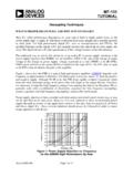
6 Three LED indicators on the 1747-UIC provide communication and Operating System RequirementsThe USB to DH-485 interface converter works with RSLinx version or higher and Windows98/2000/XP, on computers equipped with USB the Interface ConverterTo install the interface whether you will mount the interface converter. The interface converter can be mounted on a DIN rail using the DIN rail mounting kit (included). the Ferrite Collar for EMC Compliance. See page the switch (SW) on the interface converter to indicate the appropriate ensure proper ground, make cable connections between the interface converter and the DH-485 device or interface first.
7 See Connect DH-485 Devices to the Interface Converter s RS-485 Port on page 5 or Connect DH-485 Devices to the Interface Converter s RS-232 Port on page not connect more than one 1747-UIC interface converter to a single (DH485)RS232 (DH485)SWMfgXXXXMADE IN INDIAN223RS485 (DH485)RS232 (DH485)SWMfgXXXXMADE IN INDIAN223 Set for RS-232 PortSet for RS-485 Port4 Universal Serial Bus (USB) to DH-485 Interface ConverterPublication 1747-IN063C-EN-P - January the 1747-UIC USB cable into the computer s USB port. The green OK LED indicator should turn on to indicate that the 1747-UIC is receiving power through the USB this is the first time that this interface converter has been connected to this computer, you must install the 1747-UIC drivers.
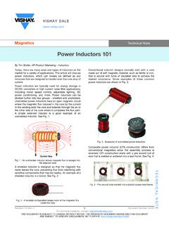
8 See Install the Drivers on page which COM port has been assigned to the interface converter. See Identify the Assigned COM Port on page an RS-232 DF1 Driver within RSLinx. See Configure the 1747-UIC Interface Converter in RSLinx on page DH-485 communications using RSWho. Both the USB and DH-485 green LED indicators should be flashing when communications are the Ferrite Collar (European EMC Compliance)Install the provided ferrite collar on the 1747-UIC cable for suppression of electromagnetic emissions and interference.
9 The collar is required for compliance with the European EMC be most effective, the ferrite collar must be placed between the cable ties on the USB cable where the cable exits the 1747-UIC interface the collar so that it encircles the the plastic housing until the collar snaps that the collar is fully stop the RSLinx RS-232 DF1 driver or shut down RSLinx prior to unplugging the interface converter from the computer s USB (DF1)RS485 (DH485)RS232 (DH485)USB to DH485 INTERFACE IN INDIAN223 LISTED collarcable tiesUniversal Serial Bus (USB) to DH-485 Interface Converter 5 Publication 1747-IN063C-EN-P - January 2006 Connect DH-485 Devices to the Interface Converter s RS-485 PortConnect the Following DH-485 Equipment to the RS-485 PortUse CableSLC 500 Fixed Controller1747-C13 SLC 5/01, SLC 5/02, and SLC 5/03 (Channel 1)
10 Controllers1747-AIC Isolated Link CouplerPanelView 300 and higher Terminals with DH-485 PortsATTENTIONTo avoid ESD damage to the 1747-UIC interface converter, always connect it to the properly grounded DH-485 device or interface prior to plugging the USB cable into the computer s USB (DH485)USB to DH485 INTERFACE IN INDIAN223 USB (DF1)LISTED Computer with USB PortPanelView 300 and Higher Te r m i n a l1747-UIC1747-AICSLC 5/01, SLC 5/02, and SLC 5/03 (Channel 1) ControllerSLC 500 Fixed Controller6 Universal Serial Bus (USB) to DH-485 Interface ConverterPublication 1747-IN063C-EN-P - January 2006 Connect DH-485 Devices to the Interface Converter s RS-232 PortConnect the Following DH-485 Equipment to the RS-232 PortUse CableSLC 5/03, SLC 5/04, and SLC 5/05 (Channel 0)(1) Controllers(1)Make sure your controller s Channel 0 configuration is set to DH-485 prior to connecting the 1747-UIC interface converter to Channel 0.