Transcription of ±15kV ESD-Protected, Slew-Rate-Limited, Low …
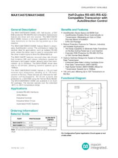
1 AVAILABLEF unctional DiagramsPin Configurations appear at end of data Diagrams continued at end of data is a trademark of Maxim Integrated Products, pricing, delivery, and ordering information, please contact Maxim Direct at 1-888-629-4642, or visit Maxim s website at DescriptionThe MAX481E, MAX483E, MAX485E, MAX487E MAX491E, and MAX1487E are low-power transceivers forRS-485 and RS-422 communications in harsh environ-ments. Each driver output and receiver input is protectedagainst 15kV electro-static discharge (ESD) shocks,without latchup. These parts contain one driver and onereceiver. The MAX483E, MAX487E, MAX488E, andMAX489E feature reduced slew-rate drivers that minimizeEMI and reduce reflections caused by improperly termi-nated cables, thus allowing error-free data transmissionup to 250kbps.
2 The driver slew rates of the MAX481E,MAX485E, MAX490E, MAX491E, and MAX1487E are notlimited, allowing them to transmit up to transceivers draw as little as 120 A supply cur-rent when unloaded or when fully loaded with disableddrivers (see Selector Guide). Additionally, the MAX481E,MAX483E, and MAX487E have a low-current shutdownmode in which they consume only A. All parts oper-ate from a single +5V are short-circuit current limited, and are protectedagainst excessive power dissipation by thermal shutdowncircuitry that places their outputs into a high-impedancestate. The receiver input has a fail-safe feature that guar-antees a logic-high output if the input is open MAX487E and MAX1487E feature quarter-unit-loadreceiver input impedance, allowing up to 128 trans-ceivers on the bus.
3 The MAX488E MAX491E aredesigned for full-duplex communications, while theMAX481E, MAX483E, MAX485E, MAX487E, andMAX1487E are designed for half-duplex applications that are not ESD sensitive see the pin-and function-compatible MAX481, MAX483, MAX485,MAX487 MAX491, and RS-485 TransceiversLow-Power RS-422 TransceiversLevel TranslatorsTransceivers for EMI-Sensitive ApplicationsIndustrial-Control Local Area NetworksNext-Generation Device Features For Fault-Tolerant Applications:MAX3430: 80V Fault-Protected, Fail-Safe, 1/4-Unit Load, + , RS-485 TransceiverMAX3080 MAX3089: Fail-Safe, High-Speed(10 Mbps), Slew-Rate-Limited, RS-485/RS-422 Transceivers For Space-Constrained Applications:MAX3460 MAX3464: +5V, Fail-Safe, 20 Mbps,Profibus, RS-485/RS-422 TransceiversMAX3362: + , High-Speed, RS-485/RS-422 Transceiver in a SOT23 PackageMAX3280E MAX3284E: 15kV ESD-Protected, 52 Mbps, +3V to + , SOT23, RS-485/RS-422 True Fail-Safe ReceiversMAX3030E MAX3033E: 15kV ESD-Protected,+ , Quad RS-422 Transmitters For Multiple Transceiver Applications:MAX3293/MAX3294/MAX3295: 20 Mbps, + ,SOT23, RS-485/RS-422 Transmitters For Fail-Safe Applications:MAX3440E MAX3444E: 15kV ESD-Protected, 60V Fault-Protected, 10 Mbps, Fail-Safe RS-485/J1708 Transceivers For Low-Voltage Applications:MAX3483E/MAX3485E/MAX3486E/ MAX3488E/MAX3490E/MAX3491E.
4 + Powered, 15kVESD-Protected, 12 Mbps, Slew-Rate-Limited, True RS-485/RS-422 Transceivers 15kV ESD-Protected, Slew-Rate-Limited, Low-Power, RS-485/RS-422 TransceiversOrdering InformationPARTTEMP RANGEPIN-PACKAGEMAX481 ECPA0 C to +70 C8 Plastic DIPMAX481 ECSA0 C to +70 C8 SOMAX481 EEPA-40 C to +85 C8 Plastic DIPMAX481 EESA-40 C to +85 C8 SOMAX483 ECPA0 C to +70 C8 Plastic DIPMAX483 ECSA0 C to +70 C8 SOMAX483 EEPA-40 C to +85 C8 Plastic DIPMAX483 EESA-40 C to +85 C8 SOOrdering Information continued at end of data Guide appears at end of data Information19-0410; Rev 4; 10/03 MAX481E/MAX483E/MAX485E/ MAX487E MAX491E/MAX1487E 15kV ESD-Protected, Slew-Rate-Limited, Low-Power, RS-485/RS-422 TransceiversSupply Voltage (VCC).
5 12 VControl Input Voltage ( R E , DE).. to (VCC+ )Driver Input Voltage (DI).. to (VCC+ )Driver Output Voltage (Y, Z; A, B) ..-8V to + Input Voltage (A, B)..-8V to + Output Voltage (RO).. to (VCC+ )Continuous Power Dissipation (TA= +70 C)8-Pin Plastic DIP (derate C above +70 C) ..727mW14-Pin Plastic DIP (derate C above +70 C)..800mW8-Pin SO (derate C above +70 C)..471mW14-Pin SO (derate C above +70 C)..667mWOperating Temperature RangesMAX4_ _C_ _/MAX1487EC_ A ..0 C to +70 CMAX4_ _E_ _/MAX1487EE_ C to +85 CStorage Temperature Range ..-65 C to +160 CLead Temperature (soldering, 10sec) ..+300 CDC ELECTRICAL CHARACTERISTICS(VCC= 5V 5%, TA= TMINto TMAX, unless otherwise noted.) (Notes 1, 2)Stresses beyond those listed under Absolute Maximum Ratings may cause permanent damage to the device.
6 These are stress ratings only, and functionaloperation of the device at these or any other conditions beyond those indicated in the operational sections of the specifications is not implied. Exposure toabsolute maximum rating conditions for extended periods may affect device MAXIMUM RATINGSPARAMETERSYMBOLMINTYPMAXUNITSD river Common-Mode OutputVoltageVOC3 VChange in Magnitude of DriverDifferential Output Voltage forComplementary Output States in Magnitude of DriverCommon-Mode Output Voltagefor Complementary Output States High Low CurrentIIN1 2 ADifferential Driver Output (no load)VOD15V2 VDifferential Driver Output(with load) Differential Input Hysteresis VTH70mVReceiver Output High Output Low (high impedance)Output Current at ReceiverIOZR 1 A12k CONDITIONSDE = 0V.
7 VCC= 0V or ,all devices exceptMAX487E/MAX1487ER = 27 or 50 , Figure 8R = 27 or 50 , Figure 8R = 27 or 50 , Figure 8DE, DI, R E MAX487E/MAX1487E,DE = 0V, VCC= 0V or , DI, R E DE, DI, R E -7V VCM 12 VVCM= 0 VIO= -4mA, VID= 200mVIO= 4mA, VID= -200mVR = 50 (RS-422) VO = 27 (RS-485), Figure 8-7V VCM 12V, all devices exceptMAX487E/MAX1487 EReceiver Input ResistanceRIN-7V VCM 12V, MAX487E/MAX1487E48k VTHIIN2 Input Current(A, B)VIN= 12 VVIN= -7 VVIN= 12 VVIN= -7 VVMAX481E/MAX483E/MAX485E/ MAX487E MAX491E/MAX1487E2 Maxim Integrated 15kV ESD-Protected, Slew-Rate-Limited, Low-Power, RS-485/RS-422 TransceiversSWITCHING CHARACTERISTICS MAX481E/MAX485E, MAX490E/MAX491E, MAX1487E(VCC= 5V 5%, TA= TMINto TMAX, unless otherwise noted.)
8 (Notes 1, 2)DC ELECTRICAL CHARACTERISTICS (continued)(VCC= 5V 5%, TA= TMINto TMAX, unless otherwise noted.) (Notes 1, 2)mA7950V VO VCCIOSRR eceiver Short-Circuit CurrentmA35250-7V VO 12V (Note 4)IOSD2 Driver Short-Circuit Current,VO= LowmA35250-7V VO 12V (Note 4)IOSD1 Driver Short-Circuit Current,VO= HighMAX1487E, R E = 0V or VCC250400350650 CONDITIONSUNITSMINTYPMAXSYMBOLPARAMETER2 30400300500 MAX481E/MAX485E, R E = 0V or VCC500900 MAX490E/MAX491E,DE, DI, R E = 0V or VCC300500 MAX488E/MAX489E,DE, DI, R E = 0V or VCC120250DE = VCC300500DE = 0 VDE = VCCDE = 0V AMAX481E/483E/487E, DE = 0V, R E = Current in Shutdown 120250 ICCNo-Load Supply Current(Note 3)DE = VCCDE = 0 VMAX483 EMAX487 EMAX483E/MAX487E, R E = 0V or VCC A52025 MAX490EC/E, MAX491EC/EMAX481E, MAX485E, MAX1487 EDriver Rise or Fall TimetR, tF32040 Figures 10 and 12,RDIFF= 54 ,CL1= CL2= 100pFMAX490EC/E, MAX491EC/EFigures 11 and 13, CL= 15pF, S2 closedFigures 11 and 13, CL= 15pF, S1 closedFigures 11 and 13, CL= 100pF, S1 closedFigures 11 and 13, CL= 100pF, S2 closedPARAMETERSYMBOLMINTYPMAXUNITSD river Enable to Output HightZH4570 Receiver Input to OutputtPLH.
9 TPHLD river Output Skew to OutputnsDriver Enable to Output LowtZL4570nsDriver Disable Time from LowtLZ4570ns|tPLH- tPHL|DifferentialReceiver SkewDriver Disable Time from HightSKDtHZ45705ns2060200 Receiver Enable to Output LowtZL2050nsReceiver Enable to Output HighDriver Input to OutputtZH2050nsReceiver Disable Time from LowtLZ2050tPLH104060nsReceiver Disable Time from HightHZ2050 MbpsMaximum Data to ShutdowntSHDN50200600tSKEW510nsCONDITION SF igures 10 and 14,RDIFF= 54 ,CL1= CL2= 100pFFigures 10 and 14, RDIFF= 54 ,CL1= CL2= 100pFFigures 9 and 15, CRL= 15pF, S1 closedFigures 9 and 15, CRL= 15pF, S2 closedFigures 9 and 15, CRL= 15pF, S1 closedFigures 9 and 15, CRL= 15pF, S2 closedMAX481E (Note 5)Figures 10 and 12, RDIFF= 54 ,CL1= CL2= 100pFMAX481E, MAX485E, MAX1487 EnsFigures 10 and 12, RDIFF= 54 , CL1= CL2= 100pFtPHL104060nsnsns2060150nskV 15A, B, Y and Z pins, tested using Human Body ModelESD ProtectionMAX481E/MAX483E/MAX485E/ MAX487E MAX491E/MAX1487 EMaxim Integrated3 15kV ESD-Protected, Slew-Rate-Limited, Low-Power, RS-485/RS-422 TransceiversSWITCHING CHARACTERISTICS MAX483E, MAX487E/MAX488E/MAX489E(VCC= 5V 5%, TA= TMINto TMAX, unless otherwise noted.)
10 (Notes 1, 2)SWITCHING CHARACTERISTICS MAX481E/MAX485E, MAX490E/MAX491E, MAX1487E(continued)(VCC= 5V 5%, TA= TMINto TMAX, unless otherwise noted.) (Notes 1, 2)2251000 Figures 11 and 13, CL= 100pF, S2 closedFigures 11 and 13, CL= 100pF, S1 closedFigures 9 and 15, CL= 15pF, S2 closed,A - B = 2 VCONDITIONSns45100tZH(SHDN)Driver Enable from Shutdown toOutput High (MAX481E)nsFigures 9 and 15, CL= 15pF, S1 closed,B - A = 2 VtZL(SHDN)Receiver Enable from Shutdownto Output Low (MAX481E)ns45100tZL(SHDN)Driver Enable from Shutdown toOutput Low (MAX481E)ns2251000tZH(SHDN)Receiver Enable from Shutdownto Output High (MAX481E)UNITSMINTYPMAXSYMBOLPARAMETERtP LHtSKEWF igures 10 and 12, RDIFF= 54 ,CL1= CL2= 100pFtPHLF igures 10 and 12, RDIFF= 54 ,CL1= CL2= 100pFDriver Input to OutputDriver Output Skew to Outputns20800nsns2000 MAX483E/MAX487E, Figures 11 and 13,CL= 100pF, S2 closedtZH(SHDN)Driver Enable from Shutdown toOutput High 2502000ns2500 MAX483E/MAX487E,Figures 9 and 15,CL= 15pF, S1 closedtZL(SHDN)Receiver Enable from Shutdownto Output Low ns2500 MAX483E/MAX487E,Figures 9 and 15,CL= 15pF, S2 closedtZH(SHDN)Receiver Enable from Shutdownto Output High ns2000 MAX483E/MAX487E, Figures 11 and 13,CL= 100pF, S1 closedtZL(SHDN)Driver Enable from Shutdown toOutput Low ns50200600 MAX483E/MAX487E (Note 5)

