Transcription of 1GROUP Chrysler - ASE Supply
1 MULTI-BATTERY ISOLATOR APPLICATION & INSTALLATION INSTRUCTIONS(For inboard & outboard marine applications refer to instruction 180119 - Marine Isolator Installation Instructions section at )The installation of a Sure Power multi-battery isolator is quite simple as long as you carefully read and understand these instructions, and most importantly review the application chart below, before you begin. First, make sure you have all the tools, wire, connectors and circuit breakers you will need. Sure Power offers a range of installation wiring kits which make the job a snap.
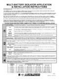
2 See the table that follows for the recommended wire size and circuit breaker for your optimum system performance it is recommended that a battery labeled "Deep Cycle" be used in the auxiliary , Sure Power multi-battery isolators are designed for alternator systems with negative ground, and batteries of the same nominal voltage. Batteries of differing voltages cannot be used. For positive ground systems, marine outboard systems, or heavy-duty truck systems, contact Sure Power for the proper isolator for you specialized READ INSTRUCTIONS COMPLETELY PRIOR TO STARTING INSTALLATION4321 GROUPGROUPGROUPGROUPG eneral Motors (Delcotron/Delphi)Except Delcotron/Delphi CS series alternators (CS series used on most 1985 and newer GM vehicles).
3 FordUp to 1998 ChryslerAll models, all years including Nippondenso externally with Nippondenso externally regulated alternatorsJapanese ImportsWith alternators using external voltage regulator or Handler Series or 8EM Remote Sense SeriesGeneral Motors (Delcotron/Delphi)Equipped with Delcotron/Delphi CS series (most 1985 - 1993) or CS130-Dseries alternators (most 1993 and newer**)JeepVehicles equipped with Delcotron/Delphi CS series alternator (most1985-1990).Toyota, Honda & Some Imports1985 and newer equipped with Nippondenso alternator with internalregulators or alternators with an "S" (sense) than Load Handler SeriesBoschRequiring regulator sensingA Group 3 Isolator will have a colored fourth terminal indicating the "R" the plug-in connector from the alternator and counting the number of holes in the connector can identify the CS series alternator.
4 The CS series will have three small and one large hole. The CS130-D alternator has four pin terminals all the same size. The SI series will have two slotted holes in the connector.**Delco/Delphi CS series alternators require a separate sense wire which is included with the connector kit. The connector kit may or may not be included with the Isolator, but is available as an Group 2 Isolators may be used in Group 1 applications. Simply disregard the additional excitation ("E") terminal. A Group 2 Isolator will have a colored fourth terminal indicating the "E" Isolators are not compatible with these alternators .
5 A Battery Separator is recommended for these applications. alternators with internal voltage sensing, some Mitsubishi and Hitachi, or single wire self exciting Delco/Delphi alternators . Isolators may be used if the alternator is modified. For further information on Group 4 Isolation Technolgy contact Sure Power 1998 and newerFordRECOMMENDED WIRE SIZE / CIRCUIT BREAKERMAXIMUMALTERNATORRATINGUp to 15ft15ft to 20ft20ft to 25ft25ft to 30ft70 Amps#8 ga. / 50 Amp#8 ga. / 50 Amp#6 ga. / 50 Amp#6 ga. / 50 Amp95 Amps#8 ga. / 50 Amp#6 ga.
6 / 50 Amp#4 ga. / 50 Amp#4 ga. / 50 Amp130 Amps#6 ga. / 80 Amp#4 ga. / 80 Amp#2 ga. / 80 Amp#1 ga. / 80 Amp160 Amps#4 ga. / 120 Amp#2 ga. / 120 Amp#2 ga. / 120 Amp#0 ga. / 120 AmpA W o r l d L e a d e r i n V e h i c l e E l e c t r o n i c E n g i n e e r i n g240 Amps#000 ga. / 150 Amp#000 ga. / 150 Amp#0000 ga. / 150 Amp#0000 ga. / 150 AmpA Group 1 Isolator will have an alternator post and up to four battery posts. There are no colored HINT FOR FORD INSTALLATIONS (1985 & LATER) This section applies to Ford alternators with 2 plug-in connections.
7 If your alternator has an output bolt, return to Step 6 of general instructions on Page : Disconnect battery before proceeding with modification and Locate the connector on the side of the alternator that has one light wire and two heavy black wires with orange or red Cut both black/orange wires close to the alternator, allowing enough length to attach a splice (approximately 2 to 3 inches). Do not cut the smaller wire. Damage to vehicle may occur if wires are cut beyond the factory cabling splice (approximately 6 inches from the alternator).3. Splice an extension wire to both wires that are attached to the alternator and connect the other end to the "A" terminal of the Splice an extension wire to both wires extending from the vehicle wire harness and connect the other end to the "1" terminal of the Return to Step #8 of general instructions, on Page : Wire colors mayvary on different modelFord vehiclesWHITE/BLACKORANGE/BLACKORANGE/BL ACKRED/BLACKRED/BLACKWHITE/BLACKORANGE/B LACKRED/BLACKEXISTING WIRENEW WIREGROUP #1 alternators .
8 FORD INSTALLATIONS WITH2 PLUG-IN CONNECTORSISOLATORT oauxiliarybattery6. Mount a circuit breaker as near to the auxiliary battery as practical, and away from engine or exhaust heat (see application chart for proper size). Connect one end of a new wire of the proper size to the "2" terminal of the Isolator. Run the wire to the circuit breaker and connect it to the "AUX" terminal. Run another wire from the circuit breaker to the auxiliary battery, connecting one end to the "BAT" terminal of the circuit breaker and the other to the positive "+" terminal of the auxiliary battery.
9 Repeat for three and four battery bank Isolators 7. IF YOUR INSTALLATION FALLS IN ALTERNATOR GROUP TYPE #2 OR #3, PROCEED TO SPECIFIC INSTRUCTIONS FOR THAT RELEVANT GROUP, OTHERWISE PROCEED TO STEP # Connect all of the auxiliary loads (phone, lights, stereo, refrigerator, winch etc.) to the positive post of the auxiliary battery(ies). Reconnect the ground cables removed in step 1. Also, make sure the negative (-) terminals of the auxiliary battery(s) are properly grounded with a conventional ground strap. Protect with circuit breakers as required. 9. Perform the electrical tests (page 4) to assure proper : 1 ALTERNATOR - 1 MAIN BATTERY (BANK) - 1 AUXILIARY (BANK)To vehicle ignitionsystem, headlights, horn, auxiliary equipmentstereo, lights, refrigerator,winch, MAINBATTERY USED ONMANY VEHICLESBATTERY 2 AUXILIARY12 ABATTERY 1 VEHICLEALTERNATOROUTPUTR emove original wire(s)from alternator - place onterminal #1 of IsolatorEXISITNG WIRENEW WIRE1.
10 Remove the wires from negative terminals of all the batteries on your vehicle. Do not run the engine, extinguish all burning material and do not smoke near the engine. FOLLOW VEHICLE MANUFACTURER'S RECOMMENDATIONS FOR DISCONNECTING Mount the isolator in a convenient location as near to the alternator as possible and away from the exhaust manifold. Allow for proper ventilation. Do not mount on the engine. Drill 1/8" holes and mount with the screws provided. 3. Install hardware to the studs in the order shown in diagram, being careful not to over torque the bottom hex or jam nut.