Transcription of 1N5711, 1N5712, 5082-2800 Series
1 1N5711, 1N5712, 5082-2800 Series Schottky Barrier Diodes for General Purpose Applications Data Sheet Description/Applications Features The 1N5711, 1N5712, 5082-2800 /10/11 are passivated Low Turn-On Voltage As Low as V at 1 mA. Schottky barrier diodes which use a patented guard ring Pico Second Switching Speed design to achieve a high break down voltage. Packaged in High Breakdown Voltage Up to 70 V. a low cost glass package, they are well suited for high level Matched Characteristics Available detecting, mixing, switching, gating, log or A-D converting, video detecting, frequency discriminating, sampling, and wave shaping.
2 The 5082-2835 is a passivated Schottky diode in a low cost glass package. It is optimized for low turn-on voltage. The 5082-2835 is particularly well suited for the UHF mixing needs of the CATV marketplace. Outline 15 Maximum Ratings (.016) . Junction Operating and Storage Temperature Range (.014) 1N5711, 1N5712, 5082-2800 /10 -65 C to +200 C. -60 C to +150 C. DC Power Dissipation ( ) (Measured in an infinite heat sink at TCASE = 25 C). MIN. (.076) . Derate linearly to zero at maximum rated temp. (.068) 1N5711, 1N5712, 5082-2800 /10 mW.
3 MW. Peak Inverse VBR. (.170) . (.150). CATHODE. ( ) . MIN. DIMENSIONS IN MILLIMETERS AND (INCHES). Package Characteristics Outline 15 Lead Lead Tin-Lead Max. Soldering 260 C for 5 sec Min. Lead 4 pounds pull Typical Package Inductance 1N5711, 1N5712:.. nH. 2800 Series :.. nH. Typical Package Capacitance 1N5711, 1N5712:.. pF. 2800 Series :.. pF. The leads on the Outline 15 package should be restricted so that the bend starts at least 1/16 inch from the glass body. Outline 15 diodes are available on tape and reel.
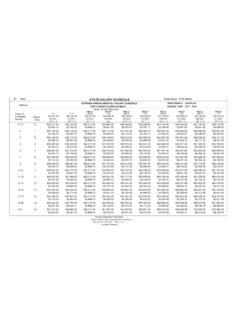
4 The tape and reel specification is patterned after RS-296-D. Electrical Specifications at TA = 25 C. General Purpose Diodes Min. Max. VF = 1 V Max. Max. Breakdown Forward at Forward Reverse Leakage Max. Part Package Voltage Voltage Current Current Capacitance Number Outline VBR (V) VF (mV) IF (mA) IR (nA) at VR (V) CT (pF). 5082-2800 15 70 410 15 200 50 1N5711 15 70 410 15 200 50 5082-2810 15 20 410 35 100 15 1N5712 15 20 550 35 150 16 5082-2811 15 15 410 20 100 8 5082-2835 15 8* 340 10* 100 1 Test IR = 10 A IF = 1 mA *VF = V VR = 0 V.
5 Conditions *IR = 100 A f = MHz Note: Effective Carrier Lifetime ( ) for all these diodes is 100 ps maximum measured with Krakauer method at 5 mA except for 5082-2835 which is measured at 20 mA.. Matched Pairs and Quads Basic Matched Matched Batch Test Conditions Part Number Pair Quad Matched[1]. 5082- Unconnected Unconnected 2800 5082-2804 5082-2805 VF at IF = , 5 mA. VF = 20 mV VF = 20 mV *IF = 10 mA. CO at f = MHz 2811 5082-2826 VF at IF = 10 mA. VF = 10 mV CO at f = MHz CO = pF. 2835 5082-2080 VF at IF =10 mA.
6 VF = 10 mV CO at f = MHz CO = pF. Note: 1. Batch matched devices have a minimum batch size of 50 devices. SPICE Parameters Parameter Units 5082-2800 5082-2810 5082-2811 5082-2835. BV V 75 25 18 9. CJ0 pF EG eV IBV A 10E - 5 10E-5 10E-5 10E-5. IS A x 10E-9 x 10E-9 x 10E-8 x 10E-8. N RS 25 10 10 5. PB V PT 2 2 2 2. M . Typical Parameters 50 100,000 150. 125. 10 10,000. IR - REVERSE CURRENT (nA). IF - FORWARD CURRENT (mA). 100 CT - CAPACITANCE (pF). 5. 75. 1000. +150 C. 1. 50 +100 C. 100. +50 C 25. +25 C. 0C 10 0.
7 50 C. T A = C. 1 0. 0 0 20 40 60 80 100 120 0 10 20 30 40 50. VF - FORWARD VOLTAGE (V) VR - REVERSE VOLTAGE (V) VR - REVERSE VOLTAGE (V). Figure 1. I-V Curve Showing Typical Figure 2. ( 5082-2800 OR 1N5711) Typical Figure 3. ( 5082-2800 or 1N5711) Typical Temperature Variation for 5082-2800 or Variation of Reverse Current (IR) vs. Reverse Capacitance (CT) vs. Reverse Voltage (VR). 1N5711 Schottky Diodes. Voltage (VR) at Various Temperatures. 100 10,000. 150. 125. IF - FORWARD CURRENT (mA). IR - REVERSE CURRENT (nA).
8 10 1000. 100. 75. 50. +150 C 100. +100 C 25. +50 C TA = C. 10. +25 C. 0C. 50 C. 0 0 5 10 15 20 25 30. VF - FORWARD VOLTAGE (V) VR - REVERSE VOLTAGE (V). Figure 4. I-V Curve Showing Typical Temperature Figure 5. (5082-2810 or 1N5712) Typical Variation for the 5082-2810 or 1N5712 Schottky Variation of Reverse Current (IR) vs. Reverse Diode. Voltage (VR) at Various Temperatures. Notes: Typical values were derived using limited samples during initial product characterization and may not be representative of the overall distribution.
9 Typical Parameters, continued 100 100,000 100. 150. 10,000. IF - FORWARD CURRENT (mA). IF - FORWARD CURRENT (mA). IR - REVERSE CURRENT (nA). 10 10. 100. 1000. 50. +150 C +150 C. 100 25 +100 C. +100 C +50 C. TA = C. +50 C +25 C. +25 C 10 0C. 0C 50 C. 50 C. 1 0 0 5 10 15 20 25 30 0 VF - FORWARD VOLTAGE (V) VR - REVERSE VOLTAGE (V) VF - FORWARD VOLTAGE (V). Figure 6. I-V Curve Showing Typical Temperature Figure 7. (5082-2811) Typical Variation of Reverse Figure 8. I-V Curve Showing Typical Temperature Variation for the 5082-2811 Schottky Diode.
10 Current (IR) vs. Reverse Voltage (VR) at Various Variations for 5082-2835 Schottky Diode. Temperatures. 100,000 1000. 5082-2800 , 1N5711. +150 C 10,000. RD - DYNAMIC RESISTANCE ( ). +125 C. IR - REVERSE CURRENT (nA). CT - CAPACITANCE (pF). 5082-2811. +100 C 100. 1000 +75 C 5082-2810/2811 5082-2811. 1N5712 1N5712. 100 +50 C. 5082-2835 10. +25 C. 10. 5082-2835. 1 0 1. 0 1 2 3 4 5 6 0 2 4 6 8 10 0 2 4 6 8 10. VR - REVERSE VOLTAGE (V) VR - REVERSE VOLTAGE (V) IF - FORWARD CURRENT (mA). Figure 9. (5082-2835) Typical Variation of Reverse Figure 10.