Transcription of 2-2 Lime Kiln Principles And Operations
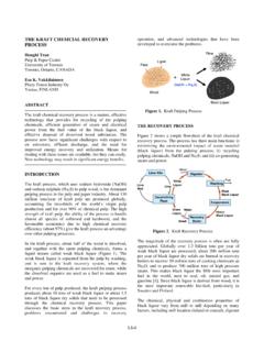
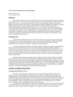
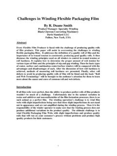
1 KILN Principles AND Operations Terry N. Adams, Technical Consultant 900 Lenora Street Unit 200 Seattle WA 98121 ROTARY LIME KILNS Slides 1 and 2 are the title and outline for the presentation. Slide 3, below, shows a schematic of the exterior of a modern rotary lime-reburning kiln. Slide 4 shows a schematic of the interior features of a lime-reburning kiln. Rotary lime kilns are large steel tubes that are lined on the inside with refractory bricks. They are slightly inclined from the horizontal and are slowly rotated on a set of riding rings. Lime mud is introduced at the uphill, feed end and slowly makes its way to the discharge end due to the inclination and rotation. A burner is installed at the downhill or discharge end of the kiln where fuel is burned to form an approximately cylindrical flame. Heat transfer from this flame and the hot combustion gases that flow up the kiln dries, heats, and calcines the counter-flowing lime solids.
2 Rotary lime kilns in the pulp and paper industry range in size from 7 ft ( m) in diameter by 175 ft (53 m) long to ft (4 m) in diameter by 400 ft (122 m) long. The refractory lining is from 6 in. ( cm) to 10 in. ( cm) thick. Production capacities for these units range from 50 tons/day of CaO (45 metric tons/day) to 450 tons/day of CaO (400 metric tons/day). The weight of the kiln is supported on riding rings that encircle the kiln. These riding rings contact carrying rolls supported by concrete piers. A large electric motor operating through a reducing gearbox and pinion drives a main gear attached to the kiln. Typically the kiln is driven at speeds of to 2 RPM, often with variable speed arrangements. Typical transit times for the lime through the kiln are from hours to 4 hours under normal operating conditions. This is set by the speed and by the slope of the kiln, which is between and 3 (5/16 to 5/8 inches/foot).
3 The rotation of the kiln necessitates the use of hoods and seals at each end for connection to stationary ancillary equipment. At the hot end, the firing hood provides support for the burner and the flame management equipment, as well as openings and passages for the discharge of the reburned lime product. At the cold end, the hood provides openings for a lime mud feed screw or belt, a connection to the induced draft fan and an important seal to limit the flow of tramp air. In older installations this hood is often an enlarged chamber in which dust and mud can be sluiced out of this area. Newer installations incorporate smaller hoods to improve the seal and shorten the length of the mud screw or belt. ROTARY KILN FLAMES The burner and flame play an important role in product quality and refractory service life. As with all combustion fired heat exchange equipment, higher flame temperatures mean higher production capacity and efficiency.
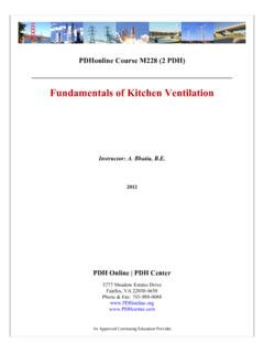
4 However, excessive temperatures cause refractory damage, and over-burned, slow-reacting lime product. This tradeoff in performance results in a compromise in flame length. Slide 5 shows sketches of three types of rotary kiln flames. Shorter flames are too hot and cause refractory damage and overburned lime, while longer flames cause some loss in production capacity and efficiency, and loss of control of the product quality. A compact, medium-length flame approximately three times the kiln diameter in length is a good tradeoff between efficiency and refractory service life. However, irrespective of the shape, the flame must not touch the refractory, or serious refractory washing will occur. ROTARY KILN CHAIN SYSTEMS At the cold end of the kiln, the relatively low gas temperature hampers heat transfer. To improve this, a section of chain is hung from the shell in this part of the kiln.
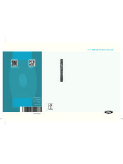
5 This chain is made up of links that are typically in. by 3 in. ( cm x cm). Hangers attach lengths of this chain directly to the kiln shell either from one end or both ends. When chain is hung from one end it is referred to as curtain chain. When hung from both ends it is most often called a garland system. Slide 6 shows sketches of these two types of chain systems, and shows the difference between high-density and low-density chain hanging arrangements. Slide 7 shows photographs of the two types of chain systems. The method of hanging the chain makes little difference in its effectiveness as a regenerative heat exchange surface. As long as the chain alternatively contacts the combustion gases and the lime mud as the kiln rotates, it is effective. Like any low-temperature heat exchanger, it is the available surface area that is most important to effectiveness. The chain surface area in a lime reburning kiln can represent two-thirds of the entire heat transfer surface.
6 ROTARY KILN REFRACTORY SYSTEMS There are several different types of refractory materials available for application in lime reburning, and usually two or three of these are used at different locations along the length of the kiln. A very common refractory system consists of bricks that are either shaped to fit the curvature of the shell or are in thin wedges that can be laid in an arch pattern in order to produce a complete shell lining. The refractory bricks are composed of special heat-resistant and chemical-attack resistant materials that are most often alumina and silica compounds. Traditionally, the bricks in the hot zone of the kiln near the flame are composed of 70% alumina in order to resist the high temperatures and chemical attack in this region. About one-third of the way up the length of the kiln, this is changed to 40% alumina bricks, which have better insulating characteristics.
7 Finally, a castable low-temperature refractory is used in the chain section at the cold end of the kiln. Many modifications of this pattern are now available including cast or packed refractories in place of bricks, or two-brick systems that use insulating bricks against the steel shell and chemical-attack resistant bricks in contact with the lime solids and combustion gases. Slide 8 shows the arrangement for a single-brick and a two-brick refractory system. The ability of the refractory lining to withstand chemical attack by the lime and its constituents is crucial to the service life of this part of the kiln. Although sudden changes in temperature can damage the lining, it is primarily due to chemical attack that refractory is washed from the kiln and requires periodic replacement. Quite aside from the increased heat loss associated with thin, worn refractory lining, it is important for structural reasons to maintain the lining to avoid exposure of the steel shell to combustion temperatures.
8 Slide 9 describes refractory wastage and presents several methods for controlling wastage. Slide 10 shows photographs of refractory wastage and refractory collapse, when the arch effect of the bricks is lost and several complete rows of bricks fall out. Slide 11 shows two other features of the interior lining of rotary kilns that are used to improve heat transfer. The first feature is a set of lifters that are installed in the cold end of the kiln, usually just downhill from the chains. Lifters mix the lime mud and expose it to the hot gases. Discharge dams are usually located at the hot end of the kiln and cause the lime to pool behind the dam underneath the flame. ROTARY KILN PRODUCT COOLERS Slide 12 shows a schematic of satellite product coolers. All modern kilns are being offered with product coolers. Satellite coolers are tubes attached to the kiln shell and rotating with the kiln.
9 The hot reburned lime product drops through holes in the shell just uphill from the lip of the kiln into the tube coolers. Internal structures move the lime back uphill in these tubes as they orbit with the kiln rotation. They also bring the hot lime into contact with air, which preheats this combustion air and results in a substantial improvement in energy efficiency for the kiln. There are now two other types of product coolers for lime reburning kilns that can be installed on new kilns or retrofit to older kilns. EXTERNAL LIME MUD DRIERS Slide 13 shows a schematic of an external lime mud drier. The wet lime mud is introduced into the duct leading to a cyclone. The mud dries in flight, separates from the gases in the cyclone, and flows into the kiln as a dry powder. The lime dust that escapes the cyclone is usually captured in an electrostatic precipitator and also enters the kiln dry.
10 With this system, chains are not needed to dry the lime mud; the entire kiln length is available for heating and calcining. LIME KILN FANS Slide 14 presents two important parts of the combustion system, the fans at the hot end and cold end of the kiln. The Primary Air (PA) fan is at the hot end and supplies a small amount of air to the burner for flame shaping and stability. Typically the PA fan supplies only 5% to 25% of the total air required for complete combustion. The Induced Draft (ID) fan at the cold end of the kiln is the main gas moving fan. It pulls the combustion products, carbon dioxide from calcining, and the water vapor from the wet mud out of the cold end of the kiln. The ID fan is used to control the total air flow into the kiln for combustion, so controls the excess air or excess oxygen in the flue gas from the kiln. The capacity of the ID fan often limits the production capacity of the kiln.