Transcription of 2-4: Stress Concentration Caused by Sudden Change in Form
1 A. K. Sengupta MET 301: Stress Concentration 1/6 2-4: Stress Concentration Caused by Sudden Change in Form A Change in the geometric shape of a part gives rise to additional Stress over and above the calculated Stress , which is known as Stress Concentration . In the part shown below, the tensile Stress changes from P/A1 to P/A2 and, as A1>A2, . Within the part, the internal Stress gets redistributed from low to high value at the region where the cross-sectional area changes. In this example, this redistribution occurs at the region of the fillet radius joining the two geometric forms. If a large fillet radius is provided between the two sections, that is the cross-sectional area is changed more gradually, then the internal stresses gets ample space to get redistributed evenly. However, if the fillet radius is small, that is the Change in shape is more abrupt, then the internal stresses do not get enough space to get redistributed evenly.
2 As a result of this, at the base of the fillet in the smaller side, the actual Stress becomes more than the theoretical Stress ( P/A2). This increase in Stress due to Sudden Change of geometric shape is called Stress Concentration . Similar to the fillet radius, holes, notches, or grooves also bring in Sudden Change in the geometric form. This means all these features will also be associated with Stress Concentration effect. Generally, more abrupt the Change in geometric form, higher is the Stress Concentration effect. Because Stress Concentration increases mechanical Stress , a better design approach is to strive to reduce Stress Concentration effect at the critical stressed areas. Following design alternatives are some creative design approach to reduce Stress Concentration . In each of the cases, the Change is section geometry has been introduced more gradually. High Stress Concentration Better design and less Stress Concentration Remark Gradual reduction in diameter of the stepped shaft More gradual Change of cross-section In many design situations, it is not possible to altogether avoid the effect of Stress Concentration .
3 For example, collars and groves are needed in shafts for bearing mounting; keyways in shafts are needed for couplings. Often holes are needed for fasteners. All these discontinuities in the part P P A. K. Sengupta MET 301: Stress Concentration 2/6 geometry cause Stress Concentration . In mechanical design, Stress Concentration effects can be minimized by placing these geometric features in a noncritical Stress area. However, in some cases, the effect of Stress Concentration must be accounted for in design calculation. It is also worthwhile to note that tool marks, porosity in castings etc. may also give rise to Stress Concentration effect. Geometric Stress Concentration factor To account for Stress Concentration effect, the actual maximum stresses have been determined either experimentally or by using more sophisticated Stress analysis methods, such as finite element analysis, for common types of geometric features.
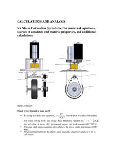
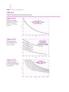
4 Based on such calculations the geometric Stress Concentration factors (K) are determined for these types of features. The Stress Concentration factor is defined as, tioncrossimummitheforstresscalculatedetc holenotchfilletonstressactualofvaluehigh estKsec.,,, The value of the factor K varies from 1 to about 3 in most cases. K= 1 means no Stress Concentration , that is, calculated value of Stress = actual value of Stress . When K = 3, the actual Stress is three times the calculated value. The values of Stress Concentration are provided in chart forms in the textbook (Figures 2-8 to 2-21). There are 14 different charts; each chart is for a specific combination of (i) type of section, (ii) type of geometric feature and (iii) type of loading. A. K. Sengupta MET 301: Stress Concentration 3/6 Example Determine the maximum theoretical Stress and actual Stress considering Stress Concentration effect in the following loading condition: THE MAX Stress WILL OCCUR AT THE CROSS SECTION WITH THE HOLE.
5 THE AREA OF THE CROSS SECTION A = (2-1/4)*1/4 = in2 Thus the MAX THEORETICAL Stress ON THE PART IS Theoretical = P/A = 5000/.4375 = 11,428 psi FOR ACTUAL Stress , FIND Stress Concentration FACTOR Kt FROM FIGURE 2-20 PAGE 145: d/W = .25/2 = Kt = Thus the actual Stress Actual = Theoretical * Kt = 11,428* = 30,057 psi P=5000 lb P=5000 lb 2 HOLE THRU THICK 2 Cross-section with the hole A. K. Sengupta MET 301: Stress Concentration 4/6 The Stress will be maximum at the top and bottom points, at the root of the fillets in the thinner portion of the part. Equal tensile and compressive Stress will be developed. M = 2,250,000 N-mm I = bd3/12 = 25*1143/12 = 3086550 mm4 Mc/I = 2,250,000 * 57/3086550 = MPa From Figure 2-17: D/d = ; r/d = 13/114 = -> Kt = Actual Kt = * = 74 MPa Cast Iron is a brittle material. Thus the maximum normal Stress theory is applicable.
6 Since, cast iron is weaker in tension, Nfs = Sut/ Actual = 200/74 = d=114 A. K. Sengupta MET 301: Stress Concentration 5/6 Ductile and brittle material, loading type, operating condition and applicability of geometric Stress Concentration factor DUCTILE MATERIAL Steady Stress : In ductile materials, when Stress exceeds yield strength (Syp) due to Stress Concentration at a point, plastic deformation is initiated at that point. It has been observed that in such a situation the plastic deformation proceeds in such a way that it reduces and ultimately eliminates the effect of Stress Concentration . Plastic deformation due to Stress Concentration is limited in a small area does not generally constitute failure of the part in most design situations. As a result of this, for ductile materials, when the Stress is applied gradually and the Stress is steady (not changing too much), Stress Concentration effects are neglected (K=1) in mechanical design calculations.
7 Impact loading: Instead of gradual loading, if the load is applied suddenly, such as an impact load, the Stress inside the material may reach to ultimate tensile strength (Su) due to Stress Concentration . The critically Stress point may not get enough time to plastically deform to mitigate the effect of Stress Concentration . When Stress reaches Su, a brittle failure occurs, that is a crack will form at the critically stressed point. This crack will form a geometric discontinuity and will cause more Stress Concentration , and as a result the crack will propagate and a rapid fracture of the part can occur. Thus, if there is an impact load on ductile material, Stress Concentration effect must be considered. Cold environment: A similar rapid fracture of a part may occur if the part operates at a low temperature condition. At a low temperature ductile materials can fail as a brittle material; that is no yielding but directly fracture; failure from formation of crack rather than a plastic deformation.
8 Thus, if a part is expected to operate in low temperature environment, geometric Stress Concentration factor should be used to determine the actual Stress , even if the part is made up of ductile material. Cyclic Stress : Another form of Stress is cyclic Stress where the direction of Stress is continuously changing from positive to negative Stress throughout the life cycle of the part. Consider the axial Stress in the piston rod in a reciprocating compressor. As long as the compressor is running, in each forward and backward stroke will induce compressive and tensile axial Stress in the piston rod. Similar kind of alternating stresses are also common for rotating shafts with bending load in one direction. The bending stresses in the outer layer of the shaft alternates between tensile and compressive Stress , as the part rotates. For all gear, belt or chain drives, similar alternating bending Stress may arise.
9 Failure of a ductile part due to purely cyclic Stress occurs in a special way. The failure is called fatigue failure and occurs at a Stress level known as endurance strength (Se) of the material. We will learn more about this fatigue loading in the next section. What is important at this point is that, the appearance of the failure surface due to fatigue loading resembles brittle failure, even if the part is made of ductile material. No plastic deformation is noticed at the failure initiation point, rather than the failure surface appears to be initiated from a crack (separation of molecular plane). Due this type of failure characteristics, we may intuitively conclude that Stress Concentration has an important role in failure for cyclic loading. A. K. Sengupta MET 301: Stress Concentration 6/6 Bbased on extensive testing of ductile materials in cyclic loading, it has been found out that the effect of Stress Concentration in cyclic loading is not as pronounced as in static loading.
10 In other words the fatigue Stress Concentration factor (Kf) has a lower value than the geometric Stress Concentration factor (K). These two Stress Concentration factors are related to each other by a material property called sensitivity index or notch sensitivity (q) in the following way: 11 KKqf The value of the q can vary between zero and 1. When q=0, Kf =1, that is, no fatigue Stress Concentration effect When q=1, Kf=K, that is, fatigue Stress Concentration has equal value of geometric Stress Concentration factor. The value of the sensitivity index of a material depends on two factors, the type of the material and its micro structure. For some commonly used ductile materials q values are provided in table 2-6 in the textbook, which varies between & For other materials q values are available from material handbooks. If q value is not readily available for a material, a conservative approach is to use q=1, that is geometric and fatigue Stress Concentration factors to have the same value.