Transcription of 2.5” & 4.5” Rear Coil Spring & 2.5” Spacer Kits
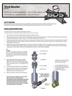
1 & Rear Coil Spring & Spacer KitsDodge 2500 Pickup | 2014 Rev. 091318 Part#: 012259, 012258, 012458491 W. Garfield Ave., Coldwater, MI 49036 . Phone: 517-279-2135 Web: . E-mail: | 012259 Read And Understand All Instructions And Warnings Prior To Installation Of System And Operation Of YOU STARTBDS Suspension Co. recommends this system be installed by a professional technician. In addition to these instructions, professional knowledge of disassembly/ reassembly procedures and post installation checks must be YOUR SAFETYC ertain BDS Suspension products are intended to improve off-road per-formance.
2 Modifying your vehicle for off-road use may result in the vehicle handling differently than a factory equipped vehicle. Extreme care must be used to prevent loss of control or vehicle rollover. Failure to drive your modified vehicle safely may result in serious injury or death. BDS Suspension Co. does not recommend the combined use of suspension lifts, body lifts, or other lifting devices. You should never operate your modified vehicle under the influence of alcohol or drugs. Always drive your modified vehicle at re-duced speeds to ensure your ability to control your vehicle under all driving conditions.
3 Always wear your seat INSTALLATIONS pecial literature required: OE Service Manual for model/year of vehicle. Refer to manual for proper disassembly/reassembly procedures of OE and related to recommendations when replacement fasteners, retainers and keepers are called out in the OE rim and tire combinations may increase leverage on suspension, steering, and related components. When selecting combinations larger than OE, consider the additional stress you could be inducing on the OE and related suspension system vehicles may experience drive line vibrations.
4 Angles may require tuning, slider on shaft may require replacement, shafts may need to be lengthened or trued, and U-joints may need to be and properly block vehicle prior to installation of BDS Suspension components. Always wear safety glasses when using power installation is to be performed without a hoist, BDS Suspension Co. recom-mends rear alterations to payload options and initial ride height variances, the amount of lift is a base figure. Final ride height dimensions may vary in accordance to original vehicle attitude.
5 Always measure the attitude prior to beginning truck is about to be fitted with the best suspension system on the market today. That means you will be driving the baddest looking truck in the neighborhood, and you ll have the warranty to ensure that it stays that way for years to come. Thank you for choosing BDS Suspension!BEFORE YOU DRIVEC heck all fasteners for proper torque. Check to ensure for adequate clearance between all rotating, mobile, fixed, and heated members. Verify clearance between exhaust and brake lines, fuel lines, fuel tank, floor boards and wiring harness.
6 Check steering gear for clearance. Test and inspect brake steering sweep to ensure front brake hoses have adequate slack and do not contact any rotating, mobile or heated members. Inspect rear brake hoses at full extension for adequate slack. Failure to perform hose check/ replacement may result in component failure. Longer replacement hoses, if needed can be purchased from a local parts head light check and all fasteners after 500 miles. Always inspect fasteners and compo-nents during routine | 3 Spacer Box KitPart #QtyDescription024971 Rear track Bar Bracket1451 track Bar Bracket Sleeve (2-1/8" long)
7 024962 Rear Coil Spacer4221 Bolt Pack43/8"-16 x 4" bolt43/8" USS flat washer83/8"-16 Prevailing torque nut024992 Rear Bump Stop911112215" Sway Bar LinkSB58BK4 Hourglass Bushing - EB16214745/8" x 12mm ID x " Sleeve6741 Bolt Pack19/16"-12 x 4" bolt29/16" SAE Thru-hardened washer19/16"-12 Prevailing torque nut13/8"-16 x 1-1/2" bolt13/8" SAE Washer13/8"-16 Serrated edge flanged nut17/16"-14 x 1-1/2" bolt27/16" SAE thru hardened washer17/16"-14 Prevailing torque x 80mm bolt410mm x 65mm bolt87/16" USS washer - clear Prevailing torque nut - clear zincCoil Spring Box KitPart #QtyDescription024971 Rear track Bar Bracket (or) Dual Drilled track Bar Bracket1451 track Bar Bracket Sleeve (2-1/8" long)
8 Rear Coil Spring Rear Coil Spring024992 Rear Bump Stop911112215" Sway Bar LinkSB58BK4 Hourglass Bushing - EB16214745/8" x 12mm ID x " Sleeve6741 Bolt Pack19/16"-12 x 4" bolt29/16" SAE Thru-hardened washer19/16"-12 Prevailing torque nut13/8"-16 x 1-1/2" bolt13/8" SAE Washer13/8"-16 Serrated edge flanged nut17/16"-14 x 1-1/2" bolt27/16" SAE thru hardened washer17/16"-14 Prevailing torque x 80mm bolt410mm x 65mm bolt87/16" USS washer - clear Prevailing torque nut - clear zinc4 | 012259 INSTALLATION INSTRUCTIONS1.
9 Park vehicle on clean flat and level surface. Block front wheels for Disconnect the rear trackbar from the axle, retain all hardware. (Fig 1)Tip: You made need to detach the vent hose clip from the track bar bracket to prevent the nut tab from puncturing the vent 13. Raise rear of vehicle and support frame rails with jack Remove the rear Support the rear axle with a hydraulic jack. 6. Disconnect the rear sway bar links from the frame and sway bar. (Fig 2)1/2 Drill012259 | 5 FIGURE 27.
10 Disconnect the rear shocks and lower the axle, retain hardware. On the driver s side it is easiest to access the top hardware by cutting the inner fender well as shown. This trim procedure is not required but greatly aids in removal and installation of the shock. (Fig 3a, 3b)8. Remove the rear coil springs and upper and lower coil Spring 3A FIGURE 3B9. Locate the holes in the rear lower coil mount. Clearance the rear most hole on the driver s side to 1/2 to accept larger hardware, the re-maining 3 holes will accept 3/8 hardware.