Transcription of 2.7V 4-Channel/8-Channel 10-Bit A/D Converters with SPI ...
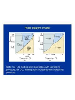
1 2008 Microchip Technology 1 MCP3004/3008 Features 10-Bit resolution 1 LSB max DNL 1 LSB max INL 4 (MCP3004) or 8 (MCP3008) input channels Analog inputs programmable as single-ended or pseudo-differential pairs On-chip sample and hold SPI serial interface (modes 0,0 and 1,1) Single supply operation: - 200 ksps max. sampling rate at VDD=5V 75 ksps max. sampling rate at VDD= Low power CMOS technology 5 nA typical standby current, 2 A max. 500 A max. active current at 5V Industrial temp range: -40 C to +85 C Available in PDIP, SOIC and TSSOP packagesApplications Sensor Interface Process Control Data Acquisition Battery Operated SystemsFunctional Block DiagramDescriptionThe Microchip Technology Inc. MCP3004/3008devices are successive approximation 10-Bit Analog-to-Digital (A/D) Converters with on-board sample andhold circuitry.
2 The MCP3004 is programmable toprovide two pseudo-differential input pairs or foursingle-ended inputs. The MCP3008 is programmableto provide four pseudo-differential input pairs or eightsingle-ended inputs. Differential Nonlinearity (DNL)and Integral Nonlinearity (INL) are specified at 1 with the devices is accomplished usinga simple serial interface compatible with the SPIprotocol. The devices are capable of conversion ratesof up to 200 ksps. The MCP3004/3008 devices operateover a broad voltage range ( - ). Low-currentdesign permits operation with typical standby currentsof only 5 nA and typical active currents of 320 A. TheMCP3004 is offered in 14-pin PDIP, 150 mil SOIC andTSSOP packages, while the MCP3008 is offered in 16-pin PDIP and SOIC TypesComparatorSampleand Hold10-Bit SARDACC ontrol LogicCS/SHDNVREFVSSVDDCLKDOUTS hiftRegisterCH0 ChannelMaxInputCH1CH7** Note: Channels 4-7 are available on MCP3008 OnlyDINVDDCLKDOUTMCP30041234141312111098 567 VREFDINCH0CH1CH2CH3CS/SHDNDGNDAGNDNCVDDC LKDOUTMCP300812341615141312111095678 VREFDINCS/SHDNDGNDCH0CH1CH2CH3CH4CH5CH6C H7 NCAGNDPDIP, SOIC, TSSOPPDIP, 4-Channel/8-Channel 10-Bit A/D Converterswith SPI Serial InterfaceMCP3004/3008DS21295D-page 2 2008 Microchip Technology : 2008 Microchip Technology 3 MCP3004 CHARACTERISTICSA bsolute Maximum Ratings Inputs and Outputs to VDD+ Temperature.
3 65 C to +150 CAmbient temperature with power 65 C to +150 CSoldering temperature of leads (10 seconds) .. +300 CESD Protection On All Pins (HBM).. 4kV Notice: Stresses above those listed under AbsoluteMaximum Ratings may cause permanent damage to thedevice. This is a stress rating only and functional operation ofthe device at those or any other conditions above thoseindicated in the operational listings of this specification is notimplied. Exposure to maximum rating conditions for extendedperiods may affect device SPECIFICATIONSE lectrical Characteristics: Unless otherwise noted, all parameters apply at VDD = 5V, VREF = 5V, TA = -40 C to +85 C, fSAMPLE = 200 ksps and fCLK = 18*fSAMPLE. Unless otherwise noted, typical values apply for VDD = 5V, TA = +25 RateConversion TimetCONV 10clock cyclesAnalog Input Sample cyclesThroughput RatefSAMPLE 20075kspskspsVDD = VREF = 5 VVDD = VREF = AccuracyResolution10bitsIntegral NonlinearityINL 1 LSBD ifferential NonlinearityDNL 1 LSBNo missing codes overtemperatureOffset Error Error PerformanceTotal Harmonic Distortion -76dBVIN = to @1 kHzSignal-to-Noise and Distortion (SINAD)
4 61dBVIN = to @1 kHzSpurious Free Dynamic Range 78dBVIN = to @1 kHzReference InputVoltage VDDVNote2 Current Drain A ACS = VDD = 5 VAnalog InputsInput Voltage Range for CH0 or CH1 in Single-Ended Mode VSS VREFVI nput Voltage Range for IN+ in pseudo-differential modeIN- VREF+IN-Input Voltage Range for IN- in pseudo-differential modeVSS-100 VSS+100mVNote 1:This parameter is established by characterization and not 100% :See graphs that relate linearity performance to VREF :Because the sample cap will eventually lose charge, effective clock rates below 10 kHz can affect linearity performance, especially at elevated temperatures. See Section Maintaining Minimum Clock Speed , Maintaining Minimum Clock Speed , for more 4 2008 Microchip Technology Current 1 ASwitch Resistance 1000 See Figure 4-1 Sample Capacitor 20 pFSee Figure 4-1 Digital Input/OutputData Coding FormatStraight BinaryHigh Level Input VDD VLow Level Input VoltageVIL VDDVHigh Level Output VIOH = -1 mA, VDD = Level Output VoltageVOL = 1 mA, VDD = Leakage CurrentILI-10 10 AVIN = VSS or VDDO utput Leakage CurrentILO-10 10 AVOUT = VSS or VDDPin Capacitance(All Inputs/Outputs)CIN,COUT 10pFVDD = (Note 1)TA = 25 C, f = 1 MHzTiming ParametersClock FrequencyfCLK = 5V (Note 3)VDD = (Note 3)
5 Clock High TimetHI125 nsClock Low TimetLO125 nsCS Fall To First Rising CLK EdgetSUCS100 nsCS Fall To Falling CLK EdgetCSD 0 nsData Input Setup TimetSU50 nsData Input Hold TimetHD50 nsCLK Fall To Output Data ValidtDO 125200nsnsVDD = 5V, See Figure 1-2 VDD = , See Figure 1-2 CLK Fall To Output EnabletEN 125200nsnsVDD = 5V, See Figure 1-2 VDD = , See Figure 1-2CS Rise To Output DisabletDIS 100nsSee Test Circuits, Figure 1-2CS Disable TimetCSH270 nsDOUT Rise TimetR 100nsSee Test Circuits, Figure 1-2 (Note 1)DOUT Fall TimetF 100nsSee Test Circuits, Figure 1-2 (Note 1)ELECTRICAL SPECIFICATIONS (CONTINUED)Electrical Characteristics: Unless otherwise noted, all parameters apply at VDD = 5V, VREF = 5V, TA = -40 C to +85 C, fSAMPLE = 200 ksps and fCLK = 18*fSAMPLE. Unless otherwise noted, typical values apply for VDD = 5V, TA = +25 1:This parameter is established by characterization and not 100% :See graphs that relate linearity performance to VREF :Because the sample cap will eventually lose charge, effective clock rates below 10 kHz can affect linearity performance, especially at elevated temperatures.
6 See Section Maintaining Minimum Clock Speed , Maintaining Minimum Clock Speed , for more information. 2008 Microchip Technology 5 MCP3004/3008 TEMPERATURE CHARACTERISTICS FIGURE 1-1:Serial Interface RequirementsOperating CurrentIDD 425225550 AVDD = VREF = 5V,DOUT unloadedVDD = VREF = ,DOUT unloadedStandby CurrentIDDS 2 ACS = VDD = Specifications: Unless otherwise indicated, VDD= + to + , VSS= RangesSpecified Temperature RangeTA-40 +85 COperating Temperature RangeTA-40 +85 CStorage Temperature RangeTA-65 +150 CThermal Package ResistancesThermal Resistance, 14L-PDIP JA 70 C/WThermal Resistance, 14L-SOIC JA 108 C/WThermal Resistance, 14L-TSSOP JA 100 C/WThermal Resistance, 16L-PDIP JA 70 C/WThermal Resistance, 16L-SOIC JA 90 C/WELECTRICAL SPECIFICATIONS (CONTINUED)Electrical Characteristics.
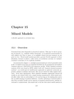
7 Unless otherwise noted, all parameters apply at VDD = 5V, VREF = 5V, TA = -40 C to +85 C, fSAMPLE = 200 ksps and fCLK = 18*fSAMPLE. Unless otherwise noted, typical values apply for VDD = 5V, TA = +25 1:This parameter is established by characterization and not 100% :See graphs that relate linearity performance to VREF :Because the sample cap will eventually lose charge, effective clock rates below 10 kHz can affect linearity performance, especially at elevated temperatures. See Section Maintaining Minimum Clock Speed , Maintaining Minimum Clock Speed , for more INTSUTHDTSUCSTCSHTHITLODOUTTENTDOTRTFLSB MSB OUTTDISNULL BITMCP3004/3008DS21295D-page 6 2008 Microchip Technology 1-2:Load Circuit for tR, tF, 1-3:Load circuit for tDIS and CL = 100 pFDOUTtRVoltage Waveforms for tR, tFCLKDOUTtDOVoltage Waveforms for tDOtFVOHVOL90%10%*Waveform 1 is for an output with internal conditions such that the output is high, unless disabled by the output control.
8 Waveform 2 is for an output with internal conditions such that the output is low, unless disabled by the output PointDOUT3k 100 pFtDIS Waveform 2tDIS Waveform 1 CSCLKDOUTtEN12B9 Voltage Waveforms for tENtEN WaveformVDDVDD/2 VSS34 Voltage Waveforms for tDISDOUTDOUTCSVIHTDISW aveform 1*Waveform 2 2008 Microchip Technology 7 MCP3004 PERFORMANCE CHARACTERISTICSNote: Unless otherwise indicated, VDD = VREF = 5V, fCLK = 18* fSAMPLE, TA = +25 2-1:Integral Nonlinearity (INL) vs. Sample 2-2:Integral Nonlinearity (INL) vs. 2-3:Integral Nonlinearity (INL) vs. Code (Representative Part).FIGURE 2-4:Integral Nonlinearity (INL) vs. Sample Rate (VDD = ).FIGURE 2-5:Integral Nonlinearity (INL) vs. VREF (VDD = ).FIGURE 2-6:Integral Nonlinearity (INL) vs. Code (Representative Part, VDD = ).Note:The graphs and tables provided following this note are a statistical summary based on a limited number ofsamples and are provided for informational purposes only.
9 The performance characteristics listed hereinare not tested or guaranteed. In some graphs or tables, the data presented may be outside the specifiedoperating range ( , outside specified power supply range) and therefore outside the warranted Rate (ksps)INL (LSB)Positive INLN egative (V)INL(LSB)Positive INLN egative CodeINL (LSB)VDD = VREF = 5 VfSAMPLE = 200 Rate (ksps)INL (LSB)Positive INLN egative INLVDD = VREF = (V)INL(LSB)Positive INLN egative INLVDD = VREF = VfSAMPLE = 75 CodeINL (LSB)VDD = VREF = VfSAMPLE = 75 kspsMCP3004/3008DS21295D-page 8 2008 Microchip Technology : Unless otherwise indicated, VDD = VREF = 5V, fCLK = 18* fSAMPLE, TA = +25 2-7:Integral Nonlinearity (INL) vs. 2-8:Differential Nonlinearity (DNL) vs. Sample 2-9:Differential Nonlinearity (DNL) vs. 2-10:Integral Nonlinearity (INL) vs.
10 Temperature (VDD = ).FIGURE 2-11:Differential Nonlinearity (DNL) vs. Sample Rate (VDD = ).FIGURE 2-12:Differential Nonlinearity (DNL) vs. VREF (VDD = ). ( C)INL (LSB)Positive INLN egative Rate (ksps)DNL (LSB)Positive DNLN egative (V) DNL (LSB)Negative DNLP ositive ( C)INL (LSB)Positive INLVDD = VREF = VfSAMPLE = 75 kspsNegative Rate (ksps)DNL (LSB)Positive DNLN egative DNLVDD = VREF = (V)DNL (LSB)Positive DNLN egative DNLVDD = VREF = VfSAMPLE = 75 ksps 2008 Microchip Technology 9 MCP3004/3008 Note: Unless otherwise indicated, VDD = VREF = 5V, fCLK = 18* fSAMPLE, TA = +25 2-13:Differential Nonlinearity (DNL) vs. Code (Representative Part).FIGURE 2-14:Differential Nonlinearity (DNL) vs. 2-15:Gain Error vs. 2-16:Differential Nonlinearity (DNL) vs. Code (Representative Part, VDD= ).FIGURE 2-17:Differential Nonlinearity (DNL) vs.