Transcription of 2.8. SANITARY SEWER DESIGN - Ivins
1 Ivins City Standard Specifications for DESIGN and Construction Part 2 Engineering and DESIGN Standards Page 69 SANITARY SEWER DESIGN DESIGN FLOWS A. All SANITARY sewers and appurtenances shall be designed to carry the DESIGN flows from all contiguous areas which may, within a reasonable period of time, be tributary thereto. B. SANITARY sewers shall be designed to carry the peak discharge as specified below: 1.
2 Laterals and collector mains: 400 gallons/capita/day 2. Interceptor and outfall mains: 250 gallons/capita/day C. Other flow rates supported by accepted engineering practice may be submitted for review by City Engineer. D. Minimum manning s n value is MINIMUM SLOPES A. The following shall be the minimum slopes to be provided, unless approved otherwise by the City: SEWER PIPE DIAMETER (inches) MINIMUM SLOPE (%) 4 6 8 10 12 15 18 21
3 24 and greater B. Any deviation from these minimum slopes will require a justification with calculations from a licensed engineer showing that a 2 foot per second velocity can be maintained even in a low flow condition. C. Where DESIGN velocities are projected to be greater than 15 feet per second, the sewers and manholes shall be protected against displacement by erosion and impact MINIMUM SIZE AND DEPTH A. Minimum pipe diameter for a SEWER main is 8 inches. B. SANITARY sewers shall be designed of sufficient depth to permit SEWER laterals from basements to be connected.
4 Exceptions may be granted in subdivisions or areas in which no basements are to be constructed. A note shall be made on the plat to prohibit basements in these areas. Ivins City Standard Specifications for DESIGN and Construction Part 2 Engineering and DESIGN Standards Page 70 C. SEWER shall be installed at a depth at least 18-inches below bottom of waterline wherever possible.
5 D. Minimum depth of a SEWER main, to top of pipe, will be not less than 36" below subgrade of roadway and a minimum of 30 below any parallel running water main. ALIGNMENT A. Provide a uniform slope and alignment between manholes. B. Provide a distance of at least ten (10) feet horizontally from any existing or proposed water main. SERVICE CONNECTIONS A. Only one property owner shall be served by each lateral connected to the public main, except in condominium type buildings. B. All SEWER laterals shall intersect the SEWER main on the top third of the SEWER main pipe. C. Offset a minimum of ten (10) feet, measured horizontally, from any culinary water line or tapping.
6 D. All SEWER laterals minimum size is as follows: TYPE OF UNIT OR RESIDENCE MINIMUM SEWER LATERAL DIAMETER (inches) Single Family 4 Townhomes (each unit) 4 Multi-Family Condominiums 4 Mobile Homes 4 Apartments 4 Commercial Establishments 6 E. Lateral size shall be based on the number of fixture units in the residence and slope of lateral. Up to 90 fixture units shall be allowed per each 4 inch lateral set at a 2 percent slope. See International Building Code for larger laterals. F. Laterals 8 inch diameter and larger shall use manholes for maintenance access in lieu of cleanouts.
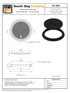
7 G. No roof drains, storm drains, foundations drains, or sub-drains shall be connected to the SANITARY SEWER system. MANHOLES A. Provide at all changes in grade, size, alignment and intersections. B. Provide at distances no greater than 400 feet apart. Ivins City Standard Specifications for DESIGN and Construction Part 2 Engineering and DESIGN Standards Page 71 C. City maintenance vehicle accessibility to all manholes is required.
8 D. Drop manholes shall be provided for a SEWER line entering a manhole at an elevation of 18 inches or more above the manhole invert. Drop must be made on exterior of manhole unless otherwise approved by City. E. Flow lines of straight through-lines (less than 10 degree horizontal bend) shall be graded through the manhole to match the average grade of the incoming and outgoing SEWER pipes. F. Flow lines of junction lines or bend lines greater than 10 degrees shall enter manhole feet higher than the outgoing line. G. When a smaller SEWER joins a large one, the invert of the larger SEWER should be lowered sufficiently to maintain the same energy gradient.
9 H. Manholes shall be a minimum 4-foot diameter. I. Manholes shall be a minimum of 5-foot diameter if any of the following conditions exist: 1. Any SEWER line is 12-inches or larger. 2. The junction of two or more inflowing sewerlines. 3. The flowline of the SEWER is 12 feet or lower than the rim. 4. Drop manholes. SEWER MAIN PIPELINES A. Located within a dedicated right-of-way, SEWER easement or equivalent. SEWER easements shall provide at least 20 feet of unobstructed width. B. Pipelines must be installed straight between manholes/inlets. Curvilinear pipes are not allowed. C. Approved Pipe Materials: 1. Solid Wall PVC, SDR 35, ASTM D3035 2.
10 Ductile Iron, cement mortar lined 3. Other materials may be approved by the City Engineer on a case by case basis. UTILTY CLEARANCES A. Sewers crossing below water mains shall be separated by a minimum vertical distance of 18 inches. B. Sewers crossing above water mains shall be laid to provide a minimum vertical distance of 18 inches between the outside of the water main and the outside of the SEWER . SEWER joints shall Ivins City Standard Specifications for DESIGN and Construction Part 2 Engineering and DESIGN Standards Page 72 be spaced as far as possible from the crossing.
