Transcription of 2. Features and benefits PESD2IVN24-T - Nexperia
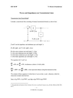
1 PESD2 IVN24-TESD protection for In-vehicle networks1 February 2018 Product data sheet1. General descriptionESD protection device in a small SOT23 (TO-236AB) Surface-Mounted Device (SMD) plasticpackage designed to protect two automotive In-vehicle network bus lines from the damage causedby ElectroStatic discharge (ESD) and other Features and benefits Reverse stand-off voltage: VRWM = 24 V Low clamping voltage: VCL= 33 V at IPP = A Typ. diode capacitance matching: Cd/Cd = % ESD protection up to 30 kV (IEC 61000-4-2) ESD protection up to 30 kV (ISO 10605; C = 330 pF, R = 330 ) ISO 7637-3: Pulse a: VS = -150 V / Pulse b: VS= +100 V Ultra low leakage current: IRM < 1 nA Qualified according to AEC-Q101 / Automotive grade3. ApplicationsESD protection for In-vehicle network lines in automotive enviroments CAN LIN FlexRay SENT4. Quick reference dataTable 1. Quick reference dataSymbolParameterConditionsMinTypMaxUn itVRWM reverse standoffvoltageTamb = 25 C--24 VIPPM rated peak pulsecurrenttp = 8/20 s[1] [2] voltageIPPM = A; tp = 8/20 s; Tamb = 25 C[3] [2]-3342V[1]According to IEC 61000-4-5.
2 [2]Measured from pin 1 or 2 to pin 3.[3]Device stressed with 8/20 s exponential decay waveform according to IEC protection for In-vehicle networksPESD2 IVN24-TAll information provided in this document is subject to legal disclaimers. Nexperia 2018. All rights reservedProduct data sheet1 February 20182 / 135. Pinning informationTable 2. Pinning informationPinSymbolDescriptionSimplifie d outlineGraphic symbol1K1cathode (diode 1)2K2cathode (diode 2)3 Kcommon cathode123TO-236AB (SOT23)21006aaa15536. Ordering informationTable 3. Ordering informationPackageType numberNameDescriptionVersionPESD2 IVN24-TTO-236 ABplastic, surface-mounted package; 3 terminals; mm pitch; x mm x 1 mm bodySOT237. MarkingTable 4. Marking codesType numberMarking code[1]PESD2 IVN24-TBV%[1]% = placeholder for manufacturing site codeNexperiaPESD2 IVN24-TESD protection for In-vehicle networksPESD2 IVN24-TAll information provided in this document is subject to legal disclaimers.
3 Nexperia 2018. All rights reservedProduct data sheet1 February 20183 / 138. Limiting valuesTable 5. Limiting valuesIn accordance with the Absolute Maximum Rating System (IEC 60134).SymbolParameterConditionsMinMaxUn itIPPM rated peak pulse currenttp = 8/20 s[1] [2] temperature-150 CTambambient temperature-55150 CTstgstorage temperature-65150 CESD maximum ratingsIEC 61000-4-2; contact discharge[2] [3]-30kVISO 10605; contact discharge;C = 330 pF, R = 330 [2] [3]-30kVVESD electrostatic dischargevoltageISO 10605; contact discharge;C = 150 pF, R = 330 [2] [3]-30kV[1]According to IEC 61000-4-5.[2]Measured from pin 1 or 2 to pin 3.[3]Device stressed with ten non-repetitive ESD ( s)040301020001aaa6304080120 IPP(%)0e-t100 % IPP; 8 s50 % IPP; 20 sFig. s pulse waveform according toIEC 61000-4-5001aaa631 IPP100 %90 %t30 ns60 ns10 %tr= ns to 1 nsFig. pulse waveform according toIEC 61000-4-2 NexperiaPESD2 IVN24-TESD protection for In-vehicle networksPESD2 IVN24-TAll information provided in this document is subject to legal disclaimers.
4 Nexperia 2018. All rights reservedProduct data sheet1 February 20184 / 139. CharacteristicsTable 6. CharacteristicsSymbolParameterConditions MinTypMaxUnitVRWM reverse standoffvoltageTamb = 25 C--24 VVBR breakdown voltageIR = 10 mA; Tamb = 25 C[1] leakagecurrentVRWM = 24 V; Tamb = 25 C[1]-150nACddiode capacitance[1]-1417pFf = 1 MHz; VR = 0 V; Tamb = 25 C[2] Cd/Cddiode capacitancematchingf = 1 MHz; VR = V; Tamb = 25 C[2] = 1 A; tp = 8/20 s; Tamb = 25 C[3] [1]-3140 VIPPM = A; tp = 8/20 s; Tamb = 25 C[3] [1]-3342 VVCL clamping voltageIPP = 16 A; tp = TLP; Tamb = 25 C[4] [1]-32-VRdyndynamic resistanceIR = 10 A; Tamb = 25 C[4] [1] [1]Measured from pin 1 or 2 to pin 3.[2] Cd is the difference of the capacitance measured between pin 1 and pin 3 and the capacitance measured between pin 2 and pin 3.[3]Device stressed with 8/20 s exponential decay waveform according to IEC 61000-4-5.
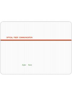
5 [4]Non-repetitive current pulse, Transmission line Pulse (TLP); square pulse; ANSI / ESD +Fig. characteristics for a bidirectional ESDprotection diodeVR (V)-25255-5-1515aaa-02749116Cd(pF)024681 01214 Fig. capacitance as a function of reversevoltage; typical valuesNexperiaPESD2 IVN24-TESD protection for In-vehicle networksPESD2 IVN24-TAll information provided in this document is subject to legal disclaimers. Nexperia 2018. All rights reservedProduct data sheet1 February 20185 / 13 VCL (V)05040302010aaa-02749290 IPP(A)0 Rdyn= 1020304050607080tp = 100 ns; Transmission line Pulse (TLP)Fig. clamping voltage (TLP); typical valuesVCL (V)-500-10-20-30-40aaa-0274930 IPP(A)-90 Rdyn= -80-70-60-50-40-30-20-10tp = 100 ns; Transmission line Pulse (TLP)Fig. clamping voltage (TLP); typical valuesaaa-027494tp (ms)10-1110102 PPP(W)110 Fig. pulse power as a function of exponentialpulse duration; typical valuesTj( C) (25 C)Fig.
6 Variation of peak pulse power as afunction of junction temperature; typical valuesNexperiaPESD2 IVN24-TESD protection for In-vehicle networksPESD2 IVN24-TAll information provided in this document is subject to legal disclaimers. Nexperia 2018. All rights reservedProduct data sheet1 February 20186 / 1350 RdCsDUT(DEVICEUNDERTEST)RG 223/U50 coaxESD TESTERIEC 61000-4-2 = 150 pF; Rd = 330 4 GHz DIGITALOSCILLOSCOPE40 dBATTENUATOR unclamped +8 kV ESD pulse waveform(IEC 61000-4-2 network)06210V(kV)-2t (ns)-1070304840201005060unclamped -8 kV ESD pulse waveform(IEC 61000-4-2 network)-8-2-62V(kV)-10t (ns)-107030-4040201005060aaa-003952 Fig. clamping test setup and waveformst (ns)-10700605040301020aaa-0274952060-201 00140 VCL(V)-60 VCL_ESD at 30 ns = 24 VFig. +8 kV pulse waveform (IEC 61000-4-2network)t (ns)-10700605040301020aaa-027496-400-804 080 VCL(V)-120 VCL_ESD at 30 ns = -22 VFig. -8 kV pulse waveform (IEC 61000-4-2network)NexperiaPESD2 IVN24-TESD protection for In-vehicle networksPESD2 IVN24-TAll information provided in this document is subject to legal disclaimers.
7 Nexperia 2018. All rights reservedProduct data sheet1 February 20187 / 1310. Application informationThe PESD2 IVN24-T is designed for the protection of two automotive IVN bus line from the damagecaused by ESD and surge BUSTRANSCEIVERCANbusPESD2 IVNxSPLIT231RT/2 RT/2 CANHCANLC ommonmode choke(optional)Fig. application: ESD protection of two automotive CAN bus linesCircuit board layout and protection device placementCircuit board layout is critical for the suppression of ESD, Electrical Fast Transient (EFT) and surgetransients. The following guidelines are the device as close to the input terminal or connector as the path length between the device and the protected parallel signal paths to a running protected conductors in parallel with unprotected all Printed-Circuit Board (PCB) conductive loops including power and ground the length of the transient return path to using shared transient return paths to a common ground ground planes whenever possible.
8 For multilayer PCBs, use ground protection for In-vehicle networksPESD2 IVN24-TAll information provided in this document is subject to legal disclaimers. Nexperia 2018. All rights reservedProduct data sheet1 February 20188 / 1311. Package outlineReferencesOutlineversionEuropeanp rojectionIssue dateIECJEDECJEITASOT23TO-236 ABsot023_po14-06-1914-09-22 Plastic surface-mounted package; 3 leadsSOT23bpDAA1 LpQHEE012 (mm are the original dimensions) XFig. outline TO-236AB (SOT23)NexperiaPESD2 IVN24-TESD protection for In-vehicle networksPESD2 IVN24-TAll information provided in this document is subject to legal disclaimers. Nexperia 2018. All rights reservedProduct data sheet1 February 20189 / 1312. (3 ) (3 ) (3 ) (3 ) soldering footprint for TO-236AB (SOT23) (2 ) (2 ) soldering footprint for TO-236AB (SOT23)NexperiaPESD2 IVN24-TESD protection for In-vehicle networksPESD2 IVN24-TAll information provided in this document is subject to legal disclaimers.
9 Nexperia 2018. All rights reservedProduct data sheet1 February 201810 / 1313. Revision historyTable 7. Revision historyData sheet IDRelease dateData sheet statusChange noticeSupersedesPESD2 IVN24-T data sheet-PESD2 IVN24-T : Marking code: correctedPESD2 IVN24-T data sheet--NexperiaPESD2 IVN24-TESD protection for In-vehicle networksPESD2 IVN24-TAll information provided in this document is subject to legal disclaimers. Nexperia 2018. All rights reservedProduct data sheet1 February 201811 / 1314. Legal informationData sheet statusDocumentstatus [1][2]Productstatus [3]DefinitionObjective[short] datasheetDevelopmentThis document contains data fromthe objective specification for [short] datasheetQualificationThis document contains data from thepreliminary [short] datasheetProductionThis document contains the productspecification.[1]Please consult the most recently issued document before initiating orcompleting a design.
10 [2]The term 'short data sheet' is explained in section "Definitions".[3]The product status of device(s) described in this document may havechanged since this document was published and may differ in case ofmultiple devices. The latest product status information is available onthe Internet at URL The document is a preview version only. The document is stillsubject to formal approval, which may result in modifications or does not give any representations or warranties as to the accuracyor completeness of information included herein and shall have no liability forthe consequences of use of such The document is a draft version only. The content is still underinternal review and subject to formal approval, which may result inmodifications or additions. Nexperia does not give any representations orwarranties as to the accuracy or completeness of information included hereinand shall have no liability for the consequences of use of such data sheet A short data sheet is an extract from a full data sheetwith the same product type number(s) and title.