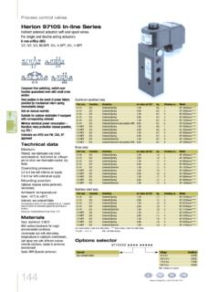
Transcription of 2 WAY (2/2) AND 3 WAY (3/2) BRASS AND …
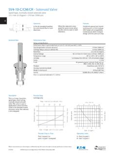
1 2 WAY (2/2) AND 3 WAY (3/2). BRASS AND stainless steel . solenoid valves . DIRECT ACTING Brochure N-289. SPECIFICATIONS. Port Size: 1/8 and1/4 solenoid Valve for air, oil, water and other fluids Flow Direction: Fixed Pressure Range: Varies, see page 2. Installation: solenoid should be vertical for maximum life Flow Factor / Cv: Varies, see page 2. Normally Closed Valve with general purpose solenoid and DIN connector. TEMPERATURE RATINGS. Seal Material Ambient Fluid NBR (Nitrile) -15 to 130 F -15 to 175 F. EPDM -10 to 130 F -10 to 175 F. FKM (Viton) - 5 to 140 F - 5 to 175 F. FEATURES. Direct acting, solenoid operated. No minimum pressure drop required. Valve internals are stainless steel and BRASS . Suitable for use on vacuum. No oil or grease used in valve assembly - less contamination of delicate equipment.
2 Normally open and normally closed designs. Wide variety of solenoids including hazardous Normally Open Valve with duty with UL, CSA, FM, CENELEC and other Hazardous Duty solenoid international listings. CLASS I DIVISION 1,2 GROUPS A,B,C,D. G Thread (parallel threads per ISO 228/1). CLASS II DIVISION 1,2 GROUPS E,F,G. Other seal materials available for many of the NEMA 4, 4X, 6, 6P, 7 & 9. models listed, PTFE, Ruby, etc. FM & CSA Certified 2 WAY (2/2) stainless steel valves . Select valve order number from table below based on such factors as: nominal size, Cv, and seat material. Select the proper solenoid based on working pressure range and either AC or DC power input. This information together with the required voltage forms a complete part number.
3 For example 24 VDC. solenoid ORDER NUMBER BASED. (1). Port Nominal Valve ON VALVE WORKING PRESSURE solenoid Seat 0701 DC 0716 DC 0201 DC 3201 & 0247 0801 DC 0813 DC. Size Size CV Order Core Mat'l 3726 DC 3724 DC 3722 DC 3722 DC 3826 DC 3824 DC. (NPT) (mm) No. Tube 3704 AC 3706 AC 3205 AC 3207 AC 3804 AC 3806 AC Dia. 3727 AC 3725 AC 3723 AC 3723 AC 3827 AC 3825 AC (mm). NORMALLY CLOSED valves WORKING PRESSURE RANGE. EPDM 9513201L. 2 .14 FKM 9513202L 0-725 0-580 0-435 0-290. PTFE 9513203L. 1/8 13mm EPDM 9513301L. 3 .24 FKM 9513302L 0-290 0-175 0-116 0-87. PTFE 9513303L. EPDM 9514201. 2 .14 FKM 9514202 0-725 0-580. PTFE 9514203. EPDM 9514301. 3 .24 FKM 9514302 0-290 0-175. PTFE 9514303. 1/4 16mm EPDM 9514401. 4 .42 FKM 9514402 0-175 0-73. PTFE 9514403.
4 EPDM 9514601. 6 .66 FKM 9514602 0-73 0-43. PTFE 9514603. Working pressure is the allowable operating pressure range for the valve 0-175 respresents 0 psig minimum and 175 psig maximum as the (1). working pressure range for the valve # 2 WAY (2/2) 1/4 BRASS valves . solenoid ORDER NUMBER BASED. (1) solenoid Nominal Valve ON VALVE WORKING PRESSURE Core Seat 0701 DC 0716 DC 0201 DC 3201 & 0247 0801 DC 0813 DC. Size Cv Order Tube Mat'l 3726 DC 3724 DC 3722 DC 3722 DC 3826 DC 3824 DC. (mm) No. Dia. 3704 AC 3706 AC 3207 AC 3207 AC 3804 AC 3806 AC (mm). 3727 AC 3725 AC 3723 AC 3723 AC 3827 AC 3825 AC. NORMALLY CLOSED valves WORKING PRESSURE RANGE. NBR 9503200. 2 .14 EPDM 9503201 0-725 0-725 0-580 0-505. FKM 9503202. 13 mm NBR 9503300. 3 .24 EPDM 9503301 0-505 0-230 0-145 0-115.
5 FKM 9503302. NBR 9504400. 4 .42 EPDM 9504401 0-200 0-115. FKM 9504402. 16 mm NBR 9504600. 6 .66 EPDM 9504601 0-70 0-30. FKM 9504602. NORMALLY OPEN valves WORKING PRESSURE RANGE. NBR 9505210. 2 .14 EPDM 9505211 0-290 0-290 0-290 0-290. FKM 9505212. 13 mm NBR 9505310. 3 .19 EPDM 9505311 0-145 0-145 0-145 0-145. FKM 9505312. (1). Working pressure is the allowable operating pressure range for the valve 0-230 represents 0 psig minimum and 230 psig maximum as the working pressure range for the valve # 2. 3 WAY (3/2) 1/4 BRASS valves . solenoid ORDER NUMBER BASED ON. (1) solenoid Nominal Seat Valve Weight (2) VALVE WORKING PRESSURE Core Size Cv Material Order (lbs.) 0701 DC 0716 DC 0201 DC 3201 & 0247 0801 DC 0813 DC. Tube Dia. (mm) No. 3726 DC 3724 DC 3722 DC 3722 DC 3826 DC 3824 DC.
6 3704 AC 3706 AC 3205 AC 3207 AC 3804 AC 3806 AC (mm). 3727 AC 3725 AC 3723 AC 3723 AC 3827 AC 3825 AC. NORMALLY CLOSED valves WORKING PRESSURE RANGE. NBR 9603210 2 .14 EPDM 9603211 0-145 0-145 0-145 0-145. FKM 9603212 13 mm NBR 9603330 3 .24 EPDM 9603331 0-116 0-116. FKM 9603332 NBR 9604430 4 .42 FKM 9604431 0-116 0-116. EPDM 9604432 16 mm NBR 9604540 5 .54 EPDM 9604541 0-101. FKM 9604542 NORMALLY OPEN valves WORKING PRESSURE RANGE. NBR 9605210 2 .14 EPDM 9605211 0-130 0-130 0-130 0-130. FKM 9605212 13 mm NBR 9605340 3 .19 EPDM 9605341 0-130. FKM 9605342 (1). Working pressure is the allowable operating pressure range for the valve 0-116 represents 0 psig minimum and 116 psig maximum as the working pressure range for the valve # (2). This is the weight with the heavier 37XX and 38XX style solenoids.
7 Deduct .50 lbs for the 0201and 32XX solenoids. SOLENOIDS. General Purpose Solenoids: General Purpose Connector: These solenoids are designed to be used with a Standard cable clamp type is included with the solenoid . mating connector which is included. The solenoid Optional connectors may be selected from the table connector combination meets NEMA 4. They are below. rated for 100% duty cycle and comply with insula- Standard Optional Connector Part Numbers tion class F (155 C). The solenoids are attached Lighted - Cable Clamp Cable to the valve with a solenoid retaining nut. The coil Clamp 1/2 NPT 24 VAC,DC 120 VAC 220 VAC. of the solenoid is a pressure molded encapsula- 0570275 0661374 0570818 0570816 0570817. tion. The electrical connection is made through three prongs (2 power, 1 ground) which attach to Options such as lighted 1/2 NPT connectors are also the mating connector with one screw.
8 See brochure available. See Brochure N-209. N-209. Hazardous duty (372X, 382X) Solenoids: Internal Wiring Schematic: Designed to be used with 1/2 NPT mating con- duit. The solenoids meet NEMA 7 and NEMA 9. requirements and are rated for a 100% duty cycle. They comply with insulation Class H (180 C), and 372X/382X Solenoids are for use in class I, groups A,B,C,D; Class II. groups E,F,G hazardous locations as defined in the National Electric Code. The solenoids are attached to the valve with a solenoid retaining nut. The elec- trical connection is made through three wire leads, (18 long). The two red leads are for power; the third lead (green with yellow stripe) is the ground. See brochure N-280 (hazardous duty solenoids). DC Solenoids AC Solenoids 3.
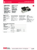
9 solenoid ELECTRICAL & TECHNICAL DATA. Power Standard Voltages Max. Temperature solenoid Location Consumption Temp. Number Approvals Fluid Code Ambient DC AC. DC (W) AC (VA). 0201 11 15 12 - 48 24 - 220. 0247 7 10 12 - 48 24 - 220 180 F T3A 140 F General Purpose 0701 16 27 12 - 48 24 - 220. 0716 7 12 - 48. 0801 16 27 12 - 48 24 - 220 180 F T3A 140 F General Purpose 0813 7 12 - 48. 3704 18 24 - 120. 3705 10 24 - 120 180 F T3A 140 F General Purpose 3706 8 24 - 220. 3207 8 24 - 220. General Purpose 3804 18 24 - 230 180 F T3A 140 F. 3806 10 24 - 230. 12. 3722. 24. 3723 120 - 220 180 F T3A 140 F. 12. 3724. 24. 12 CERTIFIED APPROVED. 3725 120 - 220. 24 LR 57643-6 File 12. 3726 180 F T3A 140 F. 24 CLASS I DIVISION 1,2 GROUPS A,B,C,D. 12 CLASS II DIVISION 1,2 GROUPS E,F,G.
10 3824 CLASS III DIVISION 1,2. 24. 3825 120 - 220. NEMA Types 1, 3, 4, 4X, 6, 6P, 7 & 9. 12. 3826 180 F T3A 140 F. 24. Insulation Class H, 356 F (180 C). 110 120. 3827. 220 - 240. See pages 2 and 3 to select proper solenoid , based on valve working pressure and Cv. 4. 2 WAY (2/2) stainless steel valves . CROSS SECTION. Normally Closed 1 Body 2 O-Ring 3 Spring 4 solenoid Plunger Assembly 5 Core Tube Assembly 6 solenoid 7 Nut VALVE DIMENSIONS. Dimensions in mm (inch). 1/8 valves with 0201 solenoid 1/4 valves with 0801 solenoid Note: To obtain the valve dimensions using other solenoids, simply substitute the dimensions from page 7 for those of the 0201 or 0801. 5. 2 WAY (2/2) BRASS valves . CROSS SECTION. Normally Closed Normally Open 1 Body 1 Upper Body 10 Seat Assembly 2 O-Ring 2 O-Ring 11 O-Ring 3 Spring 3 Upper Spring 12 Bushing 4 solenoid Plunger Assembly 4 solenoid Plunger Assy.