Transcription of 20 W Power Resistor, Thick Film Technology, TO …
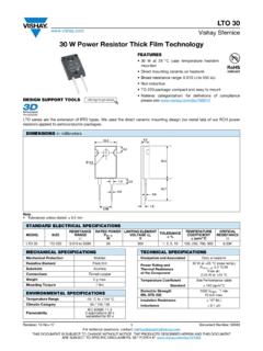
1 RTO Sfernice Revision: 16-Nov-171 Document Number: 50005 For technical questions, contact: DOCUMENT IS SUBJECT TO CHANGE WITHOUT NOTICE. THE PRODUCTS DESCRIBED HEREIN AND THIS DOCUMENTARE SUBJECT TO SPECIFIC DISCLAIMERS, SET FORTH AT W Power resistor , Thick film technology , TO-220 DESIGN SUPPORT TOOLSThe well known TO-220 package is compact and easy to 20 W at 25 C heatsink mounted High Power dissipation to size ratio Wide resistance range from to 550 k Negligible inductance Easy mounting TO-220 package: compact and easy to mount Material categorization: for definitions of compliance please see versions of this Thick film resistor are available: A radial leaded version for PCB mounting A flat lead version for surface mountingNote Tolerances unless stated: mmNote(1)E24 seriesNote Not compatible with RoHS reflow profileclick logo to get startedAvailableModelsDIMENSIONS in millimetersSTANDARD ELECTRICAL SPECIFICATIONSMODELSIZERESISTANCE RANGE RATED POWERP25 CWLIMITING ELEMENTVOLTAGE ULVTOLERANCE %TEMPERATURECOEFFICIENT ppm/ CCRITICALRESISTANCE RTO to 550K (1)
2 205001, 2, 5, 20F - 20C - FOR SURFACE Only for RTO 20 version C = during surface mount soldering temperature profile must not cause the metal tab of this device to exceed 220 SPECIFICATIONS Mechanical Protection Insulated caseResistive Element Thick filmSubstrate Alumina onto base of nickel coated copperConnections Tinned copperWeight g SPECIFICATIONS Temperature Range -55 C to 155 C Climatic Category55 / 155 / 56 SealingSealed container, solder immersionFlammability IEC 60695-11-52 applications 30 sseparated by 60 sTECHNICAL SPECIFICATIONS Dissipation and Associated Onto a heatsinkThermal Resistanceand Nominal Power20 W at + 25 CRTH (j - c): C/WFree air:2 W at +25 CDielectric StrengthMIL STD 2022000 VRMS - 1 min - 10 mA max.(between terminals and heatsink)Insulation Resistance 106 M Inductance HDIMENSIONSS tandard PackageTO-220 insulated caseRTO Sfernice Revision: 16-Nov-172 Document Number: 50005 For technical questions, contact: DOCUMENT IS SUBJECT TO CHANGE WITHOUT NOTICE.
3 THE PRODUCTS DESCRIBED HEREIN AND THIS DOCUMENTARE SUBJECT TO SPECIFIC DISCLAIMERS, SET FORTH AT For very low ohmic values, TCR for informationCHOICE OF THE HEATSINKThe user must choose the board according to the working conditions of the component ( Power , room temperature). Maximum working temperature must not exceed 155 C. The dissipated Power is simply calculated by the following ratio:P:Expressed in W T:Difference between maximum working temperature and room temperatureRTH (j - c): Thermal resistance value measured between resistive layer and outer side of the resistor . It is the thermal resistance of the component: Special Features (c - h): Thermal resistance value measured between outer side of the resistor and upper side of the heatsink. This is the thermal resistance of the interface (grease, thermal pad), and the quality of the fastening (h - a): Thermal resistance of the heatsink.
4 Example: RTH (c - a) for RTO 20 Power rating 10 W at ambient temperature +25 C Thermal resistance RTH (j - c): C/W Considering equation (1) we have: T = 155 C - 25 C = 130 C RTH (j - c) + RTH (c - h) + RTH (h - a) = = = 13 C/W RTH (c - h) + RTH (h - a) = 13 C/W - C/W = C/WPERFORMANCE TESTSCONDITIONSREQUIREMENTSM omentary OverloadEN 60115-1 2 Pr 5 s for R < 2 Pr 5 s for R 2 US < UL ( % + )Rapid Temperature Change EN 60115-1/60068-2-14 5 cycles -55 C to +155 C ( % + )Load Life EN 60115-1 1000 h Pr at +25 C (1 % + )Humidity (Steady State) EN 60115-1 56 days RH 95 % ( % + )High Temperature Exposure NF EN 140 000 1000 h - 40 % Pr at +100 C ( % + )Vibration MIL STD 202, Method 204 C Test D ( % + )Terminal Strength MIL STD 202, Method 211 Test A1 ( % + )ShockIEC 60115-1 IEC 60068-2-27 Saw tooth.
5 100 g/6 ms ( % + )RESISTANCE VALUE IN RELATION TO TOLERANCE AND TCR Resistance Values Tolerances 1 % at 10 % Typical Temperature Coefficient Range (-55 C to +155 C) 900 ppm/ C 700 ppm/ C 250 ppm/ C 150 ppm/ C P TRTH (j - c)RTH (c - h)RTH (h - a)++------------------------------------ ---------------------------------------- ---------------1 = TP-------13010--------RTO Sfernice Revision: 16-Nov-173 Document Number: 50005 For technical questions, contact: DOCUMENT IS SUBJECT TO CHANGE WITHOUT NOTICE. THE PRODUCTS DESCRIBED HEREIN AND THIS DOCUMENTARE SUBJECT TO SPECIFIC DISCLAIMERS, SET FORTH AT In any case the applied voltage must be lower than the maximum overload voltage of 750 values indicated on the graph below are applicable to resistors in air or mounted onto a Model, style, resistance value (in ), tolerance (in %), manufacturing date, vishay Sfernice CURVEPOWER CURVEPOWER RATING The temperature of the heatsink should be maintained within the limits improve the thermal conductivity, surfaces in contact should be coated with a silicone grease and the torque applied on the screw for tightening should be around 1 Nm.
6 Spring clip can also be used to mount the component on an heatsink (ex: Kunze, clip KU4-498). 1 10 100 ENERGY IN JOULES OVERLOAD DURATION IN s 10-710-610-510-410-310-210-1100 1000 10 000 100 000 Power IN W OVERLOAD DURATION IN s 10-710-610-510-410-310-210-1 PACKAGING Tube of 50 units01007550250 RATED Power IN %HEATSINK TEMPERATURE IN C20406080100120140 155120 RTO Sfernice Revision: 16-Nov-174 Document Number: 50005 For technical questions, contact: DOCUMENT IS SUBJECT TO CHANGE WITHOUT NOTICE. THE PRODUCTS DESCRIBED HEREIN AND THIS DOCUMENTARE SUBJECT TO SPECIFIC DISCLAIMERS, SET FORTH AT INFORMATION RTO 20FU685 %xxxTU50e3 MODELSTYLE CONNECTIONSF: radial leadsC: surface mountRESISTANCE VALUE TOLERANCE 1 % 2 % 5 % 10 % CUSTOM DESIGN Optional on request: special TCR, shape etc. PACKAGINGLEAD (Pb)-FREEGLOBAL PART NUMBER INFORMATIONGLOBALMODELSTYLEDIELECTRICOHM IC VALUETOLERANCEPACKAGINGRTO020F = radial leadsC = surface mountThe first four digits aresignificant figures and the last digit specifies the number of zerosto designates decimal = 48701 = 48 700 10002 = 100 000 R0100 = R6800 = 27000 = 2700 = k F = 1 %G = 2 %J = 5 %K = 10 %T = tubeSize 30 and 50:Tube 50 pieces020FR680T3 TOR0 JELegal Disclaimer Revision: 08-Feb-171 Document Number: 91000 Disclaimer ALL PRODUCT, PRODUCT SPECIFICATIONS AND DATA ARE SUBJECT TO CHANGE WITHOUT NOTICE TO IMPROVE RELIABILITY, FUNCTION OR DESIGN OR OTHERWISE.
7 vishay Intertechnology, Inc., its affiliates, agents, and employees, and all persons acting on its or their behalf (collectively, vishay ), disclaim any and all liability for any errors, inaccuracies or incompleteness contained in any datasheet or in any other disclosure relating to any makes no warranty, representation or guarantee regarding the suitability of the products for any particular purpose or the continuing production of any product. To the maximum extent permitted by applicable law, vishay disclaims (i) any and all liability arising out of the application or use of any product, (ii) any and all liability, including without limitation special, consequential or incidental damages, and (iii) any and all implied warranties, including warranties of fitness for particular purpose, non-infringement and merchantability.
8 Statements regarding the suitability of products for certain types of applications are based on vishay s knowledge of typical requirements that are often placed on vishay products in generic applications. Such statements are not binding statements about the suitability of products for a particular application. It is the customer s responsibility to validate that a particular product with the properties described in the product specification is suitable for use in a particular application. Parameters provided in datasheets and / or specifications may vary in different applications and performance may vary over time. All operating parameters, including typical parameters, must be validated for each customer application by the customer s technical experts. Product specifications do not expand or otherwise modify vishay s terms and conditions of purchase, including but not limited to the warranty expressed as expressly indicated in writing, vishay products are not designed for use in medical, life-saving, or life-sustaining applications or for any other application in which the failure of the vishay product could result in personal injury or death.
9 Customers using or selling vishay products not expressly indicated for use in such applications do so at their own risk. Please contact authorized vishay personnel to obtain written terms and conditions regarding products designed for such license, express or implied, by estoppel or otherwise, to any intellectual property rights is granted by this document or by any conduct of vishay . Product names and markings noted herein may be trademarks of their respective owners. 2017 vishay INTERTECHNOLOGY, INC. ALL RIGHTS RESERVED