Transcription of 200 HC - Sowles
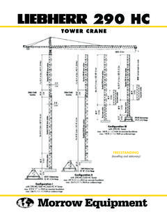
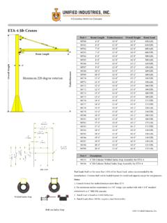
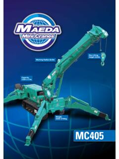
1 Morrow EquipmentFREESTANDINGT raveling & StationaryConfiguration Iwith 200 hc /290 HC/550 HC Towermax. 313 ft ( ) HUH on concrete foundationmax. 340 ft ( ) HUH on undercarriage7 x 19'-0" ( ) = 133'-0" ( )40'-9" '-3" Transition19'-0" ft ( )NOTE! See hook height charts 200 hc tower sections290 HC base towerBase tower sectionStandard 200 hc tower sectionsLong tower section40'-9" x 13'-7" ( ) = 122'-3" ( )29'-0" 550 HC tower sections27'-11" '-7" '-0" IIIwith 200 hc Towermax. 163 ft ( ) HUH on concrete foundationmax. 178 ft ( ) HUH on undercarriage9 x 13'-7" ( ) = 122'-3" ( )290HC tower sections2 x 13'-7"2 x 200 hc tower sections9 x 13'-7" ( ) = 122'-3" ( )16'-3" Undercarriage19'-8" ( ) Gauge2 x 13'-7"2 x Undercarriage19'-8" ( ) Gauge550HC Undercarriage32'-10" ( ) Gauge290HC tower sectionsConfiguration IIwith 200 hc /290 HC Towermax.
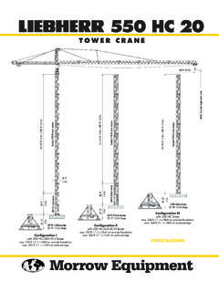
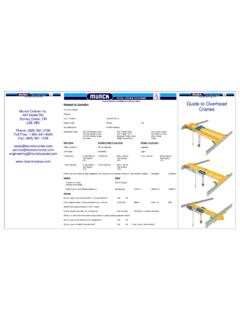
2 202 ft ( ) HUH on concrete foundationmax. 217 ft ( ) HUH on undercarriage 200 HCTOWER CRANEM orrow Equipment Co., 200 HC56'-5" '-3" ft ( )Jib Tip Radius: 201'-5" ( )8'-5" ! See hook height charts ft ( )158 ft ( )142 ft ( )120 ft ( )104 ft ( )10,470 lbs4 750 kg14,110 lbs6 400 kg5,070 lbs2 300 kg8,270 lbs3 750 kg6,280 lbs2 850 kg17,750 lbs8 050 kg19'-0" '-10" '-0" x 13'-7" ( ) = 122'-3" ( )Standard 200 hc tower sectionsBase tower sectionNOTE! Consult Morrow for specificinformation regarding alternate foun-dation details, dimensions, reactionforces and slab opening top climbing unit from crane prior to operating crane at maximum hook top climbing unit to base of crane prior to operating crane at maximum hook ofTowerHook HeightHook HeightTowerConfigurationConcrete Foundation 10m UndercarriageSectionsI1550HC 1200HC ofTowerHook HeightHook HeightTowerConfigurationConcrete Foundation 6m UndercarriageSectionsII0290HC 2200HC ofTowerHook HeightHook HeightTowerConfigurationConcrete Foundation 6m UndercarriageSectionsIII0200HC 2200HC !
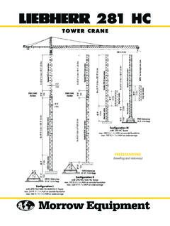
3 Please consult crane'soperation manual before erecting,operating and dismantling ! Alternate tower combinations are possible. Contact Morrow foradditional HEIGHTSJib Tip Radius: 185'-0" ( )Jib Tip Radius: 163'-1" ( )Jib Tip Radius: 146'-8" ( )Jib Tip Radius: 125'-0" ( )Jib Tip Radius: 108'-7" ( )10"265mmFREESTANDING(stationary)Morrow Equipment Co., 200 HCTOP CLIMBING with 200 hc Tower Sections(tied to structure)[Site conditionsdependent]Tie-in collarCenterlineof CraneFace ofStructureAnchor shoeTie-inStrutsTIE-IN ASSEMBLY(plan view)4 x 13'-7" ( ) = 54'-4" ( ) x 13'-7" ( ) = 95'-1" ( ) x 29'-0" ( ) + 3 x 13'-7" ( ) = 69'-9" ( ) x 29'-0" ( ) + 7 x 13'-7" ( ) = 124'-1" ( ) x 13'-7" ( ) = 122'-3" ( ) max.
4 *8'-6" ( ) min.[Site conditionsdependent]NOTE! If hook height exceeds 330 ft(100m), the number of tower sections abovethe uppermost tie-in location MUST be re-duced by 1 tower section.*Lower the top climbing unit to the upper-most tie-in prior to operating crane atmaximum hook height. *Hydraulic TopClimbing UnitNOTE! The tie-in assembly shown is an ex-ample of a typical installation. Please note,however, that factors determining the instal-lation of tie-in assemblies may vary due toproject specific criteria. Contact Morrow forinformation regarding dimensions, reactionforces, tie-in locations and slab '-7" '-7" '-7" x 13'-7" ( ) = 122'-3" ( )35'-7" '-5" '-7" '-3" ( )Min.
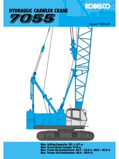
5 Hook positionBOTTOM CLIMBING with 200 hc Tower Sections(inside structure)Hydraulic bottomclimbing unitFOUNDATION DETAILS with 200 hc Base Tower(on concrete slab) 200 hc base sectionReinforcingsteel each wayFoundation anchors (4)6'-6" '-6" '-2" each wayPlan ViewElevationDirection of jibwhen climbing. Connection plateby contractorTie-InAssemblyRadius and CapacitiesMorrow Equipment Co., Lineft6070809098104110120130142150158164 170180187197 RadiusMax Capacity ft17,635 lbs ftlbs 17,635 16,525 14,795 13,120 11,355 10,715 10,140 9,1258,4457,5607,1306,6606,3706,1405,665 5,4255, 000 kg 8 0007 4956 7105 9505 1504 8604 6004 1403 8303 4303 2353 0202 8902 7852 5702 4602 300180 ft22,045 lbs ftlbs 20,770 18,000 15,790 14,180 12,500 11,800 11,090 10,050 9,1908,3607,8107,3607,0556,7906, 000 kg 9 4208 1707 1606 4305 6705 3505 0304 5604 1703 7903 5403 3403 2003 0802 850158 ft22,045 lbs ftlbs 22,045 20,000 17,570 15,660 13,930 13,140 12,300 11.
6 250 10,250 9,3708,7508, 000 kg 10 000 9 0707 9707 1006 3205 9605 5805 1004 6504 2503 9703 750142 ft22,045 lbs ftlbs 22,045 21,960 19,450 17,330 15,475 14,640 13,650 12,350 11,42010, 000 kg 10 000 9 9608 8207 8607 0206 6406 1905 6005 1804 750120 ft22,045 lbs ftlbs 22,045 22,045 21,630 19,400 17,370 16,430 15,28014, 000 kg 10 000 10 000 9 8108 8007 8807 4506 9306 400104 ft22,045 lbs ftlbs 22,045 22,045 22,045 20,930 18,76017, 000 kg 10 000 10 000 10 000 9 4908 5108 050 Tower Crane Model 200 HC2-Part LineJib Radiusin feet30405060708090104120142158180197in ,000 lbs/9 525 kg18,000 lbs/8 165 kg15,000 lbs/6 805 kg12,000 lbs/5 445 kg9,000 lbs/4 080 kg6,000 lbs/2 720 kg3,000 lbs/1 360 kg06,280 lbs2 850 kg5,070 lbs2 300 kg17,750 lbs8 050 kg8,270 lbs3 750 kg17,635 lbs (8 000 kg)2-Part Line14,110 lbs6 400 kg10,470 lbs4 750 kg22,045 lbs (10 000 kg)SPECIFICATIONSM orrow Equipment Co.
7 , kW40 - 131 - 262 fpm12 - 40 - 80 m/minSwing (fluid coupling)2 x hp2 x rpmTraveling (fluid coupling)2 x 10 hp2 x kW82 m/min480 V 3-phase 60 Hz 225 AmperesPower RequirementsDrive UnitHorsepowerKilowattsSpeedHoist Speed and Capacity123 Hoist UnitWiW 281 RX 0572-Part LineGearCapacity Line SpeedCapacityLine Speed108 hp (80 kW) AC hoist unit3-speed gearboxElectromagnetic gear shiftingEddy current brake2L-142up to 22,045 lbs@108 fpmup to 10 000 kg@33 m/minup to 9,920 lbs@289 fpmup to 4 500 kg@88 m/minup to 3,970 lbs@587 fpmup to 1 800 kg@ 179 m/minMotor Information Tower Crane Model 200 HCNOTE!
8 Capacities and line speeds indicated will vary depending on the amount of hoist rope installed. This crane model may be equipped with a hoist unit other than thatspecified in the data above. To verify, check the serial number of the crane and refer to the Liebherr 200 hc Operation Manual for additional subject to change without prior notice. For additional information, contact Morrow , GA Charlotte, NC Chicago, IL Denver, CO Honolulu, HI Houston, TX Los Angeles, CA Las Vegas, NVMillwood, NY St. Louis, MO San Francisco, CA Seattle, WA Miami, FL Tampa, FL Washington, DCSydney, Australia Wellington, New Zealand Vancouver, BC, Canada Toronto, ON, Canada M xico DF, M xico3218 Pringle Road SE P O Box 3306 Salem, Oregon 97302-0306 USATel.
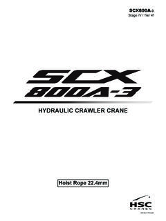
9 Fax. EquipmentC O M P A N Y, L. L. American home ofComponent List 200 HCNOTE: Weights and dimensions are approximate. Scale components before operator s cab, swing motors, slewing ring, slewing ring support and climbing shoes. Two climbing shoes are detachable; deduct 100 lbs (45 kg) each. Dimensions shown are withoutdetachable climbing operator s cab and swing slewing ring, slewing ring support and climbing shoes. Two climbing shoes are detachable; deduct 100 lbs (45 kg) each. Dimensions shown are without detachable climbing 108 hp (80 kW) hoist unit, electrical panel and handrails.
10 Does not include wire counterjib sections #1, #3, pendant bars and handrails. Counterjib A is required for jibs 180 ft ( ) and counterjib sections #1, #2, #3, pendant bars and handrails. Counterjib B is required for the 197 ft ( ) Assemblies include jib sections, pendant bars, pendant bar connecting pins and plates, trolley drive unit, trolley wire rope and Section 39'-6" x 6'-0" x 6'-5"4,870 lbs# x x 2 210 kgJib Section 39'-3" x 5'-4" x 6'-0"3,595 lbs# x x 1 630 kgJib Section 17'-8" x 5'-4" x 6'-2"1,145 lbs# x x kgJib Section 39'-2" x 5'-4" x 6'-0"3,375 lbs# x x 1 530 kgJib Section 22'-10" x 5'-4" x 6'-0"1,600 lbs# x x kgJib Section 39'-3" x 5'-4" x 6'-0"2,170 lbs# x x kgJib Section 6'-11" x 6'-0" x 6'-1"620 lbs# x x kgJib Assembly 7198'-9" x 6'-0" x 6'-5"20,295 lbs197-ft ( )