Transcription of 200 series reverse-osmosis systems - dristeem …
1 200 series reverse- osmosis systemsInstallation, Operation, and Maintenance ManualWATER TREATMENTREAD AND SAVE THESE INSTRUCTIONSiiDRISTEEM WATER TREATMENT systems INSTALLATION, OPERATION, AND MAINTENANCE MANUAL .. WARNINGS AND CAUTIONS iii dristeem WATER TREATMENT systems INSTALLATION, OPERATION, AND MAINTENANCE MANUALW arnings and cautions Warnings and Cautions WARNINGA ttention installerRead this manual before installing, and leave this manual with product owner. This product must be installed by qualifi ed HVAC and electrical contractors. Installation must be code electrical powerDisconnect electrical power before installing supply wiring or performing service or maintenance procedures on any part of the system . Failure to disconnect electrical power could result in fi re, electrical shock, and other hazardous conditions. These hazardous conditions could cause property damage, personal injury, or death.
2 CAUTIONO perate system at above-freezing the system at temperatures below freezing can damage the system or cause other property pumping and water treatment maintained pumping and water treatment equipment can cause the system to fail. Refer to the maintenance section of this IOM for recommended not install the system using steel or galvanized-steel piping and and steel-galvanized piping and joints can corrode and cause system damage. Use plastic tubing and joints when assembling all instructions in this manual to maintain product IN THE FOLLOWING INFORMATION FOR YOUR RECORDSDate of purchase_____Customer's name_____Model number_____Serial number_____ivDRISTEEM WATER TREATMENT systems INSTALLATION, OPERATION, AND MAINTENANCE MANUAL .. WARNINGS AND CAUTIONS .. iiFill in the following information for your records ..iiiATTENTION INSTALLER .. 1 Where to find more information .. 1 OVERVIEW ..2 system specifications .. 2 Flow schematic.
3 3 Component identification .. 4 system installation .. 5 Line 1 .. 5 Line 2 .. 5 Line 3 .. 5 Line 4 .. 5 Line 5 .. 5 Pre-treatment connection .. 6 series 200 controller specifications .. 6 Power .. 6 Inputs .. 6 Outputs .. 6RO pump wiring .. 8 Inlet wiring .. 8 Pressure fault switch .. 8 Pretreat switch .. 8 Tank full switch .. 8 OPERATION ..9 system operation .. 9 system operation continued .. 10 Initial system start-up .. 10 system flush .. 10 Normal operations .. 10 Shutdown .. 10 Table of contents1 dristeem WATER TREATMENT systems INSTALLATION, OPERATION, AND MAINTENANCE MANUALT able of contentsATTENTION INSTALLERRead this manual before manual with product Technical Support800-328-4447 WHERE TO FIND MORE INFORMATIONOur website:The following documents are available on our web site: Water Treatment systems Catalog Vapor-logic Controller Installation and Operation ManualDriCalc :DriCalc, our software for system sizing and selection, can be ordered at our web us at 800-328-4447 Obtaining documents from our web site or from DriCalc is the quickest way to view our literature, or we will be happy to mail literature to dristeem literatureMost dristeem product manuals are available our website.
4 11 Maintenance information .. 11 Maintenance tips .. 11 When to change cartridge filters .. 11 When to clean membranes .. 11 Membrane cleaning and preservative cartridges .. 11 Membrane cleaning in the RO system .. 12 How does it work? .. 12 Scale cleaning cartridge.. 12 Cleaning procedure .. 12 Organic cleaning cartridge .. 13 Cleaning procedure .. 13 Membrane preservative cartridge .. 14 Preserving procedure .. 14 Flushing out preservative/restart procedure .. 14 Tools .. 15 Procedure .. 15 Procedure .. 16 Tools .. 17 Low pressure cut-out switch .. 17 Operating do's and don'ts .. 17Do .. 17 Don't .. 17 WARRANTY .. 202 dristeem WATER TREATMENT systems INSTALLATION, OPERATION, AND MAINTENANCE MANUAL .. system specifi cationsOVERVIEWNOTES:1. All systems rated at 50 F (10 C) using 1000 ppm sodium chloride (NaCl) solution. system capacity decreased signifi cantly with decrease in feed water Chlorine requirements for the feed water are:a.
5 Thin-Film (standard) 0 ppm3. Feed water must be filtered to a turbidity of less than 1 system recovery (permeate to concentrate ratio) must be maintained at the recommended level. A higher than recommended recovery will lead to a premature fouling of the membrane with a loss of permeate flow and permeate 2-1:Pressurized RO holding tank specificationsModelHzMotor HPVolts*/AmpsPhase/Frequency201202203601 /3110-120 (208-240 )1/60Hz* 115V or 230V must be ordered specifi callyTable 2-2: RO station specificationsModel201202203 Rated capacity, fl ow (reject) (adjustable as needed)Gallons/minute0 - - - pressure, psi100 - 150100 - 150100 - 150 F ( C)10/5010/5010/50 Pre-fi ltersSediment cartridge - 5 micron111 Carbon cartridge - 10 micron111 Pressure switch settingsLow pressure (for pump protection)8 psi8 psi8 psi3 dristeem WATER TREATMENT systems INSTALLATION, OPERATION, AND MAINTENANCE MANUALFlow schematicOVERVIEWFIGURE 3-1: FLOW SCHEMATICOM-78224 dristeem WATER TREATMENT systems INSTALLATION, OPERATION, AND MAINTENANCE MANUAL.
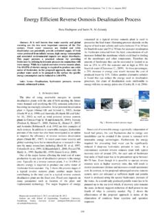
6 Component identifi cationFIGURE 4-1: COMPONENT IDENTIFICATIONT able 4-2: Component identificationItemDescription1 ControllerPower On/Off and status display2 Inlet solenoid valveNormally closed. Opens when power is fi lter pressure gauges (in-right/out-left)Measure the feed and effl uent pressure of the cartridge fi lters. Pressure difference determines when cartridge change out is fi lter5 micron sediment fi fi lter10 micron extruded carbon cartridge to remove chlorine and reduce organics from the feed pressure switchShuts the system down if the inlet pressure is lower than 8 psi (adjustable).7 High pressure pump and motorRotary pump and motor to pressurize the incoming modulesRO membrane elements housed in stainless steel pressure pressure gaugesMeasure the system (feed) and concentrate (effl uent) pressure of the membrane control valveTo adjust system pressure. Must not be completely closed when the system is in valveTo adjust and maintain adequate fl ow thru membranes12 TDS monitorMonitors the feed and permeate water - feed sensor; 12b - permeate sensor13 Permeate check valvePrevents backfl ow into RO dristeem WATER TREATMENT systems INSTALLATION, OPERATION, AND MAINTENANCE MANUALINSTALLATIONS ystem installation1.
7 Locate RO system with adequate clearance from walls and other equipment to enable membrane Run five polyvinyl tube lines to the system as follows:LINE 1 Connect raw water feed supply to the solenoid valve inlet in front of the fi rst cartridge fi lter housing. This will require inch threaded pipe fi tting and adaptor for the feed line. If desired, install an isolation valve in this line; ensure the valve opening does not restrict the water fl 2 Run a inch line from the open end of the concentrate valve to a drain. Ensure that no liquids from other lines near this drain fl ow back through this 3 Run a inch line from one of the two permeate outlets on the back of the system to the pressurized permeate storage : The recirc fl ow line is pre-connected at the 4 Run a inch line from the other permeate outlet to the humidifi er or end process being fed by the 5 Run a inch line from the pressurized relief solenoid to a drain. Ensure that no liquids from other lines near this drain fl ow back through this 5-1: SOLENOID VALVE INLETFIGURE 5-2: RECIRC FLOW LINECAUTIONPump and system performance will be adversely affected if the feed/suction line is rm all lines are connected before plugging in unit WATER TREATMENT systems INSTALLATION, OPERATION, AND MAINTENANCE MANUAL.
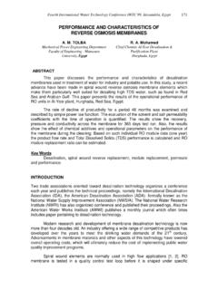
8 PRE-TREATMENT CONNECTIONIf you have pre-treatment equipment and you wish to shut-down the RO system during backwash or regeneration, a microswitch is required (standard with dristeem water softeners).1. Wire the microswitch to terminal labeled PreTreat inside controller. When the equipment goes into backwash or regeneration, the pre-treat limit switch opens and turns the power off the inlet solenoid valve, which then turns the RO pump off (and back on) when the cycle is 200 CONTROLLER SPECIFICATIONSPOWERE ither 110-120 VAC or 208-240 VAC, 1 phase, 50/60 Hz, +10/-15%, wattsInput power is auto selectedINPUTST hree switch inputs, selectable normally open or normally closedOUTPUTSRO pump 1HP (based on service factor of max)Inlet solenoid 5A20A maximum total loadNOTE: All six switches are factory set to the OFF reset (disabled)Pressure fault retry (disabled)Tank full restart time delay (two seconds)Input contact type (NC, open to operate)If you desire to change any switch functions, move that switch to the ON installationFIGURE 6-1: CONTROL BOARDCAUTIONThe controller is rated for maximum 20 amp total load.
9 Terminal strip P11 is dry contact for input signals from tank full, pressure fault and pretreat lockout. Use a small gauge 2 conductor cable for these wire 6-1:Switch positionsSwitchOff positionOn position1 Auto reset offAuto reset on2 Retries disabledRetries enabled32 sec. restart15 min. switchesSwitch 5 and 6 not dristeem WATER TREATMENT systems INSTALLATION, OPERATION, AND MAINTENANCE MANUALS chematic drawingINSTALLATIONFIGURE 7-1: CONTROLLER ELECTRICAL SCHEMATICOM-78218 dristeem WATER TREATMENT systems INSTALLATION, OPERATION, AND MAINTENANCE MANUAL .. Control boardRO PUMP WIRINGThe RO pump connects to P4 (L1) and P5 (L2) RO pump terminals. This output can operate 110/240 VAC motors up to 1HP WIRINGThe inlet solenoid valve connects to P6 (L1) and P7 (L2) inlet FAULT SWITCHThe feed pressure switch is connected to the pressure fault input. Low pressure (factory preset 8 psi) will shut system SWITCHIn systems with pretreatment, a pretreat lockout switch can be connected to the pretreat input.
10 This switch should operate when the pretreatment device is out of service. NOTE: The output from the pretreatment device must be a dry contact and must not supply FULL SWITCHDriSteem systems use a pressure switch to keep the pressurized storage tank between 30-50 psi (207-345 kPa). The switch is connected to the tank full 8-1: CONTROLLER ELECTRICAL SCHEMATICTank full9 dristeem WATER TREATMENT systems INSTALLATION, OPERATION, AND MAINTENANCE MANUALOPERATIONThe unit has a single mode of operation ON with six sub-modes or states as indicated by the steady or fl ashing panel lights. Any light condition other than steady power ON indicates the unit is effectively in standby-mode. If there are no lights, the system is OFF and all outputs are turned off. In the operating mode, the unit operates automatically. All inputs are monitored and the outputs are controlled accordingly. Pressing the power key will toggle the unit from off to operate or from operate to off.