Transcription of 2003 GUIDELINE for CALCULATING THE EFFICIENCY OF …
1 2003 . GUIDELINE for CALCULATING . THE EFFICIENCY . OF energy . recovery . VENTILATION. AND ITS EFFECT. ON EFFICIENCY . AND SIZING OF. BUILDING HVAC. SYSTEMS. GUIDELINE V. 4100 N. FAIRFAX DR., SUITE 200 ARLINGTON, VIRGINIA 22203. IMPORTANT. SAFETY DISCLAIMER. ARI does not set safety standards and does not certify or guarantee the safety of any products, components or systems designed, tested, rated, installed or operated in accordance with this standard/ GUIDELINE . It is strongly recommended that products be designed, constructed, assembled, installed and operated in accordance with nationally recognized safety standards and code requirements appropriate for products covered by this standard/ GUIDELINE . ARI uses its best efforts to develop standards/ guidelines employing state-of-the-art and accepted industry practices. ARI does not certify or guarantee that any tests conducted under its standards/ guidelines will be non-hazardous or free from risk.
2 Note: This is a new GUIDELINE . Price $ (M) $ (NM) Copyright 2003 , by Air-Conditioning and Refrigeration Institute Printed in Registered United States Patent and Trademark Office TABLE OF CONTENTS. SECTION PAGE. Section 1. Purpose ..1. Section 2. Scope ..1. Section 3. Definitions ..1. Section 4. Information Section 5. General Principles ..4. Section 6. CALCULATING the recovery EFFICIENCY Ratio for the energy recovery Ventilation Component ..4. Section 7. Integrating the EFFICIENCY of the energy recovery Component with the EFFICIENCY of Cooling and Heating Equipment ..5. Section 8. CALCULATING the Effect of energy recovery Ventilation on Cooling System EFFICIENCY ..6. Section 9. CALCULATING the Effect of energy recovery Ventilation on Heating System EFFICIENCY ..6. Section 10. Section 11. APPENDICES. Appendix A. References - Appendix B. References - Informative.
3 8. Appendix C. Sample Calculations - Appendix D. Comparing Typical Combined EFFICIENCY and energy Analysis Results in a Variety of Climates FIGURE. Figure 1. Generic Configuration of an Air-to-Air Heat Exchanger Used for energy recovery in Ventilation Applications ..2. TABLE FOR APPENDICES. Table D1. Sample Calculation Results for Five ARI GUIDELINE V- 2003 . CALCULATING THE EFFICIENCY OF energy recovery . VENTILATION AND ITS EFFECT ON EFFICIENCY AND. SIZING OF BUILDING HVAC SYSTEMS. Section 1. Purpose Coefficient of Performance (COP). A ratio of the cooling/heating capacity in watts [W] to the power input Purpose. The purpose of this GUIDELINE is to establish values in watts [W] at any given set of Rating Conditions a method of CALCULATING the energy EFFICIENCY of applied expressed in watts/watt [W/W]. energy recovery Ventilation components and of heating, ventilating, and/or air-conditioning systems utilizing such Combined EFFICIENCY (CEF).
4 The EFFICIENCY of a components at selected operating conditions. It also system incorporating an ERV component with a unitary provides guidance on proper sizing of cooling and heating packaged air conditioner, heat pump, etc. Units vary equipment when such energy recovery components are according to the application. CEF may be expressed in applied. Btu/(W h) or in W/W. Intent. This GUIDELINE is intended for the Effectiveness. The measured energy recovery guidance of the industry, including engineers, Effectiveness not adjusted to account for that portion of the installers, contractors and users. It provides a means psychrometric change in the leaving supply air (Figure 1, for CALCULATING the impact of applied energy recovery Station 2) that is the result of leakage of entering exhaust air equipment on the energy EFFICIENCY of the heating, (Figure 1, Station 3) rather than exchange of heat or ventilating and air-conditioning system at a single moisture between the airstreams.
5 The equation for selected operating condition. The GUIDELINE is not a determining Effectiveness is given in ARI Standard 1060, rating system for energy recovery Ventilation Appendix C. (ERV) Equipment, nor does it provide a means of estimating annual energy use. energy EFFICIENCY Ratio (EER). A ratio of the cooling capacity in Btu/h to the power input values in watts at any Review and Amendment. This GUIDELINE is given set of Rating Conditions expressed in Btu/(W h). subject to review and amendment as technology advances. energy recovery Ventilation (ERV) Equipment. Units which employ air-to-air heat exchangers to recover energy from exhaust air for the purpose of pre-conditioning Section 2. Scope outdoor air prior to supplying the conditioned air to the space, either directly or as part of an air-conditioning (to Scope. This GUIDELINE applies to energy recovery include air heating, air cooling, air circulating, air cleaning, ventilation component applications and combinations of humidifying and dehumidifying) system.
6 Also referred to as energy recovery components with unitary heating, the air-to-air heat exchanger (AAHX). ventilating, and air-conditioning equipment incorporating mechanical ventilation with outside air. Heat Pipe Heat Exchanger. A device employing tubes charged with a fluid for the purpose This GUIDELINE applies only to energy of transferring sensible energy from one air stream to recovery applications utilizing components tested and another. Heat transfer takes place through the rated in accordance with ARI Standard 1060. vaporization of the fluid exposed to the warmer air stream and condensation of the fluid in the cooler air Because non-certified data is required for stream. the calculations, the results should not be considered to be certified . Plate Heat Exchanger. A device for the purpose of transferring energy (sensible or total) from one air stream to another with no moving parts.
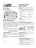
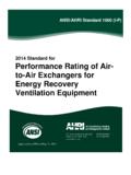
7 This Section 3. Definitions exchanger may incorporate parallel, cross or counter flow construction or a combination of these to All terms in this document follow the standard industry achieve the energy transfer. definitions in the current edition of ASHRAE Terminology of Heating, Ventilation, Air Conditioning and Refrigeration and ASHRAE Standard 84, unless otherwise defined in this section. 1. ARI GUIDELINE V- 2003 . Station 4 Station 3. Leaving Exhaust Air Entering Exhaust Air (Exhaust Air) (Return Air). AAHX. Entering Supply Air Leaving Supply Air (Outdoor Air) (Supply Air). Station 1 Station 2. Figure 1. Generic Configuration of an Air-to-Air Heat Exchanger Used for energy recovery in Ventilation Applications Rotary Heat Exchanger. A device Net Supply Air Flow. That portion of the leaving incorporating a rotating cylinder or wheel for the supply air (Figure 1, Station 2) that originated as entering purpose of transferring energy (sensible or total) supply air (Figure 1, Station 1).
8 The Net Supply Air Flow is from one air stream to the other. It incorporates heat determined by subtracting air transferred from the exhaust transfer material, a drive mechanism, a casing or side of the AAHX from the gross air flow measured at the frame, and includes any seals, which are provided to supply air leaving the heat exchanger and is given by the retard the bypassing and leakage of air from one air equation: stream to the other. Net Supply Leaving supply . Exhaust Air Transfer Ratio (EATR). The tracer gas = (1 EATR ). concentration difference between the leaving supply air Air Flow air flow . (Figure 1, Station 2) and the entering supply air (Figure 1, Station 1) divided by the tracer gas concentration difference Outdoor Air Correction Factor. The entering supply between the entering exhaust air (Figure 1, Station 3) and air flow (Figure 1, Station 1) divided by the measured the entering supply air (Figure 1, Station 1) at the 100% (gross) leaving supply air flow (Figure 1, Station 2).
9 Rated air flow rate, expressed as a percentage. Pressure Drop. The difference in static pressure Fan/Motor EFFICIENCY , Fan/Motor. The product of the between the entering air and the leaving air for a given fan EFFICIENCY and the motor EFFICIENCY including drive airstream. losses (mechanical, electrical and/or electronic as applicable) for each airstream. Exhaust Pressure Drop. The difference in static pressure between the entering exhaust air Net Effectiveness. The measured energy recovery (Figure 1, Station 3) and the leaving exhaust air Effectiveness adjusted to account for that portion of the (Figure 1, Station 4). psychrometric change in the leaving supply air (Figure 1, Station 2) that is the result of leakage of entering exhaust air Supply Pressure Drop. The difference in (Figure 1, Station 3) rather than exchange of heat or static pressure between the entering supply air moisture between the airstreams.
10 The derivation of Net (Figure 1, Station 1) and the leaving supply air Effectiveness is given in ARI Standard 1060, Appendix C. (Figure 1, Station 2). 2. ARI GUIDELINE V- 2003 . Published Rating. A statement of the assigned values Blower Power. A value for blower power input is of those performance characteristics at stated Rating required to perform the Combined EFFICIENCY calculation. If Conditions, by which a unit may be chosen for its manufacturer's data for blower power is not available, it application. These values apply to all ERV Equipment of may be calculated from component pressure loss and like size and type (identification) produced by the same Fan/Motor EFFICIENCY in accordance with this section and manufacturer. The term Published Rating includes the rating of all performance characteristics shown on the unit or published in specifications, advertising or other literature Pressure Drop.