Transcription of 2005 03 Calculation of Underground Cable Ampacity
1 CYME International T&D, 2005 1 Abstract This paper introduces the heat transfer mechanisms in Underground Cable installations and analyzes the available solution methods of the diffusion equation. The heat sources and thermal resistances of the different layers of a Cable installation are described. The basic concepts behind the Neher-McGrath method (IEEE) are discussed, along with its differences with the IEC standards for Underground Cable installations. The available commercial computer programs, designed to perform Ampacity calculations are listed along with a description of the modeling capabilities of CYME's CYMCAP. Index Terms Ampacity . Underground Cables. Neher-McGrath. IEC Standards. CYMCAP. Cables. I. INTRODUCTION TO Cable Ampacity MPACITY is a term given by Del Mar in 1951 to the current-carrying capacity of a Cable .
2 Ampacity in an Underground Cable system is determined by the capacity of the installation to extract heat from the Cable and dissipate it in the surrounding soil and atmosphere. The maximum operating temperature of a Cable is a function of the damage that the insulation can suffer as a consequence of high operating temperatures. The insulation withstands different temperatures as function of the duration of the current circulating in the conductors. There are three standardized Ampacity ratings: steady state, transient (or emergency) and short-circuit. Only steady state Ampacity ratings are discussed in this paper. Ampacity Calculation techniques are as old as the cables themselves. Anders has summarized the history of Ampacity calculations in his 1997 book [1]. There are analytical and numerical approaches to calculate Cable Ampacity .
3 The two major international standard associations, the IEEE and the IEC, have adopted the analytical methods as the basis for their standards [2], [3-9]. The numerical approaches are mainly based on finite differences or finite elements techniques. The finite elements technique is better suited for Cable Ampacity because of the round geometry of cables. This paper focuses on the analytical techniques for the computation of Cable Ampacity in steady-state through the use of assumptions that simplify the problem. For transient (or emergency) calculations the reader is referred to [1], [8], [9], [12] and [13]. Calculation of short-circuit ratings is described in [14] for both adiabatic and non-adiabatic conditions. II. AN OVERVIEW OF HEAT FLOW There are three physical mechanisms for heat transfer: Conduction Convection Radiation Fourier Law describes the heat transferred by conduction.
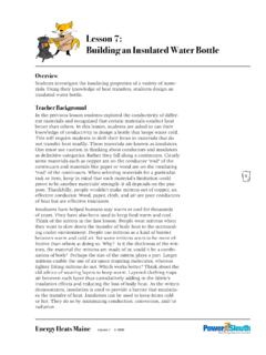
4 In very simple terms, the heat flux is proportional to the ratio of temperature over space. In an Underground Cable installation heat conduction occurs everywhere except in the air space in the conduit. Convection of heat occurs in moving fluids (air, water, etc.) and obeys Newton's Law. The flow of heat is proportional to the temperature difference. In an Underground Cable installation convection takes place in the air space inside the ducts and at the surface of the earth. The Stefan-Boltzmann Law describes the radiation of heat phenomenon as being proportional to the difference the temperatures at the power of four (tf4 t04). In Underground cables radiation of heat occurs from the Cable (s) to the ducts. Figure 1 show a typical temperature distribution for a duct bank installation using an engineered backfill on top of the duct bank.
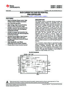
5 From the figure one can appreciate the diffusion of heat that occurs in Underground Cable systems. Diffusion is a process by which heat is transferred for one region to another in a slow, space-limited fashion described by decaying exponentials. Therefore, there is a practical distance, away from the heat source, beyond which the heating effects are not felt. Figure 1. Typical temperature distribution of an Underground Cable installation Calculation of Underground Cable Ampacity Francisco de Le n CYME International T&D 1485 Roberval, Suite 104 St. Bruno, Quebec, Canada, J3V 3P8 Tel. (450) 461 3655 A CYME International T&D, 2005 2 III. HEAT SOURCES IN Cable SYSTEMS The heat sources in Cable installations can be divided into two generic groups: heat generated in conductors and heat generated in insulators. Figure 2 shows a complex Cable construction, for illustration purposes, containing many of the possible layers in a Cable .
6 The losses in the metallic (conductors) elements are by far the most significant losses in a Cable and they are caused by: (a) Joule losses due to impressed currents, circulating currents or induced (eddy current) losses; (b) Hysteresis losses in conductors that are also magnetic. The following metallic components of a Cable system will produce heat: Core conductors Sheaths Concentric neutrals Armors Skid wires Pipes/ducts The losses in those components are functions of the frequency (f.) and the temperature (t) of operation and proportional to the square of the current (I). Customarily, the dependency with temperature and frequency is included in an equivalent ac resistance to express Joule law as: (1) Insulating materials also produce heat. The heat produced in the insulating layers is only important under certain high voltage conditions.
7 The following components could be considered: Main insulation Shields Screens Jackets Beddings/servings The loss relationship is given by: (2) where C is the capacitance, V is the voltage applied and is the loss angle. Figure 2. Illustration of a complex Cable construction IV. HEAT FLOW IN Underground Cable INSTALLATIONS In an Underground Cable system the main heat transfer mechanism is by conduction. With the exception of the air inside the conduits in duct banks or buried ducts installations all the heat is transferred by conduction. Since the longitudinal dimension of a Cable is always much larger than the depth of the installation, the problem becomes a two-dimensional heat conduction problem. In Cartesian coordinates one must solve the diffusion equation given by [1]: (3) where: = Thermal conductivity of the material c = Volumetric thermal capacity of the material W = Rate of energy (heat) generated Equation (3) cannot be solved in closed form for the complicated geometry of an Underground Cable arrangement (see Figure 1).
8 Additionally, numerical solutions could not be obtained in the pre-computer era (before 1950's). However, cables are being installed since the 1890's. Furthermore, since numerical solutions, considering all particularities of the installation, require of the solution of a large number of linear (or nonlinear) equations only with the powerful computers available nowadays, it is becoming practical to get numerical solutions for Cable rating purposes. In view of the complications of the Ampacity problem, engineers found practical solutions by combining analytical solutions to simplified geometries with heuristic results. In particular the use of thermal-electrical analogies with empirical work has been very popular with Cable engineers. To that effect, the paper published by Neher and McGrath in 1957 [10] is remarkable; they summarized the knowledge on the Ampacity Calculation field to that date, and today (2005), the Neher-McGrath method is still being used and it is the base for the IEEE and the IEC standards.
9 V. THE NEHER-MCGRATH METHOD The technique known as the Neher-McGrath method for Ampacity calculations is based on a thermal-electrical analogy method due to Pashkis and Baker (1942) [11]. The basic idea is to subdivide the study area in layers. Then one substitutes the heat sources by current sources, the thermal resistances by electrical resistances and the thermal capacitances by electrical capacitances. Figure 3 shows the correspondence between the Cable installation components and the electric circuit elements for steady state Ampacity calculations. Note that the capacitances play no part in steady state ratings. To find the Ampacity we first note that the potential of every node in the circuit is analog to the temperature of the regions between the layers. Thus, the potential difference between the terminals of the circuits and the innermost current source represents the temperature rise of the core of the Cable with respect to the ambient temperature.
10 Therefore the temperature 2),(ItfRWac=)tan(22 VCVGWdd==ttyxtcWytyxtyxtyxtx =+ + ),,(),,(1),,(1 CYME International T&D, 2005 3of the Cable 's core is the ambient temperature plus t; see Figure 4. tconductorT4T3T2T1 WcWsWa Wd Wdtambienttexterior Figure 3. Thermal-electrical equivalent Figure 4. Electrical equivalent From Figure 4 we can compute t as follows: ()( )()432121 TTWWWWTWWWTWW tasdcsdcdc++++++++ += (4) To derive an expression from where the Ampacity can be computed directly, the heat sources (electrical losses) W 's are expressed as proportion of the conductor losses (Wc). The conductor losses are computed using the ac resistance and the current. Thus, by substituting the following expressions: (5) in (4) and re-arranging we have: ))(1()(43211432121 TTRTRTTTTWtIacacd+++++++ = (6) From expression (6) one can compute the Ampacity of a Cable .