Transcription of 2010: IMPROVED ELECTROMAGNETIC INTERFERENCE …
1 IMPROVED ELECTROMAGNETIC INTERFERENCE shielding efficiency OF EPOXY COMPOSITE RESIN BY FLUORINATED CARBON NANOTUBE ADDITIVES Byong Chol Bai, Ji Sun Im and Young-Seak Lee Department of Applied Chemistry and Biological Engineering, Chungnam National University, Daejeon, 305-764, Republic of Korea Introduction EMI can be shielded by the reflection and adsorption of ELECTROMAGNETIC radiation. However, metals have several disadvantages, including high density, proneness to corrosion and physical rigidity. As an alternative, composites with conducting fillers such as metal particles, carbon black, carbon fibers and carbon nanotubes (CNTs) have been extensively employed for EMI shielding [1].
2 The direct fluorination method under a gas reaction has received especially large amounts of attention due to its potential for uniform modification, efficiency , short reaction times and low cost. In our study, we attempted dispersion by direct fluorination treatment on the surface of CNTs. We also investigated fluorination effects on multi-walled CNT (MWCNT) additives with respect to the EMI shielding efficiency by the developed conductive network in epoxy. Experimental Materials Diglycidyl ether of bisphenol A (DGEBA) (YD128, viscosity: 11,500 13,500 cps, Kukdo Chemical Co Ltd.)
3 , Korea) was used as the epoxy monomer. Triarylsulfonium hexafluoro-phosphate (mixed, 50% in propylene carbonate, Aldrich Chemical Co.) was used as the photo-initiator. Multi-walled carbon nanotubes (MWCNTs, inner diameter: 2 15 nm, length: 1 10 mm, Aldrich Co.) were used as the conducting filler. Fluorine (Messer Grieheim GmbH, ) and argon ( ) gas were used for surface treatment. Fluorination of MWCNTs Fluorination of the surface of MWCNTs was carried out by a fluorination apparatus, which consists of a reactor, a vacuum pump and buffer-tank-connected gas cylinders.
4 Non-treated MWCNTs and fluorinated MWCNTs treated at different pressures are referred to as follows: R-MWCNTs, F05-MWCNTs and F10-MWCNTs, respectively. Blend preparation A certain amount of MWCNTs ( g) was dispersed in ethanol (50 ml). In order to release the bundles, the MWCNT and ethanol mixture was sonicated for 3 h. Next, the epoxy monomer (20 g) was added into the mixture and stirred at 2000 rpm for 4 h. After stirring, in order to remove the ethanol, the mixture was kept at 80 C in an oven for 6 h. Procedure of irradiation curing The photo-initiator (1 g) was added into the prepared blend and then stirred at 2000 rpm and 70 C for 5 h.
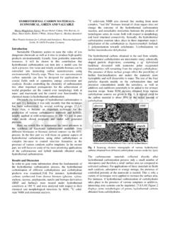
5 The blend was poured into a 150 mm x 150 mm x 2 mm aluminum mold that was treated with a release agent. E-beams were irradiated at a dose rate of 300 kGy/h in atmosphere for 10 min. Characterization of samples UV spectrometry (Optizen 2120 UV, Mecasys, Korea) was used to investigate the dispersion of CNTs in ethanol. In order to investigate fluorination effects on the MWCNTs, the change of surface morphology was investigated by field-emission transmission electron microscope apparatus (FE-TEM, JEM-2100F HR) at 200 kV. The oriented and defected carbon structures were examined using Raman analysis to determine the effects of heat treatment temperature and fluorination.
6 The XPS spectra of the MWCNTs used in this study were obtained with a MultiLab 2000 spectrometer (Thermo Electron Co., England) to evaluate the changes of chemical species on the surface of the MWCNTs before and after fluorination. Permittivity, magnetic permeability and EMI shielding efficiency (SE) were obtained according to the ASTM D-4935-99 method using a network analyzer (Agilent, E5071A) equipped with an amplifier and a scattering parameter (S-parameter) test set over a frequency range of 800 MHz 4 GHz [2]. Results and Discussion Surface morphology of fluorinated MWCNTs The change of surface morphology was investigated by TEM images.
7 Even though the significant change was not found roughly, some of amorphous carbon structures on the outside of wall were removed through fluorination treatment. Defect and graphite structures Raman spectra of the MWNCTs are illustrate the defect and graphite structures. In three samples, peaks related to defect and graphite structures (called D and G peaks) were observed at 1356 and 1585 cm-1, respectively. Chemical bonds by fluorination In XPS, the strongest peak corresponded to C1s from the MWCNTs in all samples, and with the fluorination treatment, F1s and F KL1 were observed, indicating the existence of fluorine on the surface of the MWNCTs.
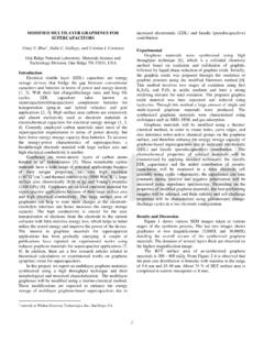
8 The atomic composition of the R-MWCNTs was carbon and oxygen. This oxygen may come from the environmental atmosphere. In the case of the fluorinated MWCNTs, the carbon, oxygen and fluorine contents of the F05-MWCNTs and F10-MWCNTs were , and and , and , respectively. Permittivity and magnetic permeability analysis The permittivity of the samples is presented in Fig. 1. In all of the samples, the real permittivity of the sample was higher than the imaginary permittivity. The epoxy showed an average real permittivity of about , and the composite of the R-MWCNTs, and epoxy exhibited a value around , an increase of more than a factor of 2.
9 The average real permittivity increased up to in the composite of the F10- MWCNTs and epoxy because the dispersion of MWCNTs may be IMPROVED in the epoxy matrix by the fluorination of MWCNTs. In addition, it can be expected that the adhesion can be IMPROVED by hydrophobic groups functionalized by fluorination treatment based on the similar hydrophobicity between the epoxy and fluorinated MWCNTs. The fluorination effects for IMPROVED adhesion properties have been presented also by other groups with consideration of surface energy changes [3,4].
10 The permeability of the samples is shown in Fig. 2. Corresponding with the results of permittivity, the real permeability was higher than the imaginary permeability, and it increased with the addition of MWNCTs and the effect of fluorination treatment. This is caused by the excellent magnetic properties of MWCNTs. The average real magnetic permeability IMPROVED up to and by the addition of the R-MWCNTs and F-10 MWCNTs, respectively. Fig. 1 Permittivity of samples; (a) and (a ): real and imaginary permittivity of F10-MWCNTs/epoxy, (b) and (b ): real and imaginary permittivity of F05-MWNCTs/epoxy, (c) and (c ): real and imaginary permittivity of R-MWCNTs/epoxy, (d) and (d ): real and imaginary permittivity of epoxy.