Transcription of 24 Flush Mount DeFlector Vent: sKMD24F0As
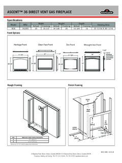
1 24" Flush Mount DeFlector Vent: sKMD24F0As . INSTALLATION INSTRUCTIONS. Parts includes: Important notes to the installer Qty. Part number Read all of the Installation Manual that is included with the Microwave Drawer before installing in the Flush Mount PREF-B019 MRP0. configuration. Flush Mount 1 DeFlector Vent Observe all governing codes, ordinances, and safety instructions. Be sure to leave these instructions with the consumer. LX-CZB055 MRE0. 2. Mounting screws 1. Prepare cabinet opening as shown in Figures 1, 2A, 2B, 2C. A A. 6" ( mm). B. B. Suggested electrical outlet location C. C. Anti-Tip block D. 5" (127 mm). E. D. E. 3-1/2" ( mm). G. F.
2 F. 4" ( mm). H. G. 24-3/16" ( mm) minimum I K. Note: the face of the shelf must sit 1 3/4" ( mm) back from 24-1/2" ( mm) maximum L M the face of the cabinet. H. 14-13/16" ( mm) to bottom of J. Anti-Tip block N. shelf face O I. 1-1/16" ( mm). J. 23-1/2" ( mm) minimum depth cabinet face K. 22-1/8" ( mm). L. 1-3/4" ( mm). M. 16-7/8" ( mm) opening N. Floor must support 100 lb ( kg). O. 1-3/4" ( mm). Figure 1. Anti-Tip block Mounting cleat A. 22" ( mm) mounting cleat opening width B. 1/4" ( mm). C. 1-1/16" ( mm). Cabinet Drawer face B C face A. CL. Top view Note: the mounting surface of the finished cleat must sit 1 1/16" ( mm) back from the face of the cabinet [pushing the face of the drawer out 1/4" ( mm)].
3 Figure 2A. E1. TINSEB 5 41 MRR 2. 3. Place the drawer adjacent to the wall or cabinet opening. Plug No oven the power supply cord into the electrical outlet. A 4. Carefully guide the drawer into the prepared opening. Avoid contact with the sides of the cutout opening and also pinching Suggested electrical outlet location Anti-Tip block B the cord between the oven and the wall. 5. Slide the drawer all the way back until the mounting flanges touch the cleats mounted in the cabinet opening. C. 6. Open the drawer. Using the 4 holes on the drawer as a template, pre drill the cabinet using a 1/16 ( mm) bit. See Figure 4. Figure 2B Front view A. 22-1/8" ( mm) mounting cleat opening width B.
4 24-3/16" ( mm) minimum 24-1/2" ( mm) maximum Flush opening width C. 3/4" ( mm) shelf Mounting Move oven location downward for extended flange countertops for better viewing angle. Figure 4. Anti-Tip block 16 7/8". ( mm). Flush opening height 3/4" ( mm). shelf 7. Secure the drawer with the 4 screws supplied. Front face of cabinet 1 3/4" ( mm). front face of shelf Figure 2C. Side view 2. Install DeFlector as shown in Figure 3A. Shelf detail showing the DeFlector vent during installation. Position DeFlector vent and mark holes. Pre drill using a 1/16" ( mm) bit before mounting. Figure 3A. Shelf detail showing the DeFlector vent installed. Figure 3B.
5 E2. 30" Flush Mount DeFlector Vent: SKMD30F0AS. INSTALLATION INSTRUCTION. Parts includes: Important notes to the installer Qty. Part number Read all of the Installation Manual that is included with the Microwave Drawer before installing in the Flush Mount PREF-B020 MRP0. configuration. Flush Mount 1 DeFlector Vent Observe all governing codes, ordinances, and safety instructions. Be sure to leave these instructions with the consumer. LX-CZB055 MRE0. 2. Mounting screws 1. Prepare cabinet opening as shown in Figures 1, 2A, 2B, 2C. A. B A. 6" ( mm). C B. Suggested electrical outlet location D. E C. Anti-Tip block D. 5" (127 mm). F E. 3-1/2" ( mm). G H F.
6 4" ( mm). Note: the face of the shelf must G. 30-5/16" ( mm) minimum I K. sit 1 3/4" ( mm) back from 30-5/8" ( mm) maximum M. L J the face of the cabinet. H. 14-13/16" ( mm) to bottom of N Anti-Tip block shelf face O I. 1-1/16" ( mm). J. 23-1/2" ( mm) minimum depth cabinet face K. 28-7/16" ( mm). L. 1-3/4" ( mm). M. 16-7/8" ( mm) opening N. Floor must support 100 lb ( kg). Figure 1 O. 1-3/4" ( mm). Anti-Tip block Mounting cleat A. 28-1/2" ( mm) mounting cleat opening width B. 1/4" ( mm). C. 1-1/16" ( mm). Cabinet Drawer face B C face A. CL. Note: the mounting surface of the finished cleat must sit 1 1/16" ( mm) back Top view from the face of the cabinet [pushing the face of the drawer out 1/4" ( mm)].
7 Figure 2A. E3. 3. Place the drawer adjacent to the wall or cabinet opening. Plug No oven the power supply cord into the electrical outlet. Suggested electrical A. 4. Carefully guide the drawer into the prepared opening. Avoid outlet location Anti-Tip block contact with the sides of the cutout opening and also pinching B. the cord between the oven and the wall. 5. Slide the drawer all the way back until the mounting flanges C touch the cleats mounted in the cabinet opening. 6. Open the drawer. Using the 4 holes on the drawer as a template, pre drill the cabinet using a 1/16 ( mm) bit. See Figure 4. Figure 2B Front view A. 28-7/16" ( mm) mounting cleat opening width B.
8 30-5/16" ( mm) minimum 30-5/8" ( mm) maximum Flush opening width C. 3/4" ( mm) shelf Move oven location Mounting downward for extended flange countertops for better viewing angle. Anti-Tip Figure 4. block 16 7/8". ( mm). Flush opening height 3/4" ( mm). shelf 7. Secure the drawer with the 4 screws supplied. Front face of cabinet 1 3/4" ( mm). front face of shelf Figure 2C. Side view 2. Install DeFlector as shown in Figure 3A. Shelf detail showing the DeFlector vent during installation. Position DeFlector vent and mark holes. Pre drill using a 1/16" ( mm) bit before mounting. Figure 3A. Shelf detail showing the DeFlector shield installed. Figure 3B.
9 1 Sharp Plaza Suite 1, Mahwah, New Jersey 07495-1123, USA 1-800-BE-SHARP (237-4277). 335 Britannia Road East, Mississauga, Ontario, L4Z 1W9, Canada E4.