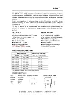
Transcription of 24C32 24C64 Bookly Micro
1 1 Rev. B01/09/07 Copyright 2007 Bookly Micro , Inc. All rights reserved. BM reserves the right to make changes to this specification and its products at any timewithout notice. BM assumes no liability arising out of the application or use of any information, products or services described herein. Customers are advised toobtain the latest version of this device specification before relying on any published information and before placing orders for serial CMOS EEPROMJANUARY 2007 DESCRIPTIONThe 24C32 and 24C64 are electricallyerasable PROM devices that use the standard 2-wire interface for communications.
2 The 24C32and 24C64 contain a memory array of 32K-bits (4K x 8) and 64K-bits (8K x 8), device is organized into 32 byte pages forpage write EEPROM operates in a wide voltage range to to be compatible with most applicationvoltages. designed this device family to be apractical, low-power 2-wire EEPROM devices are available in 8-pin PDIP, 8-pinSOIC, 8-pin TSSOP, 8-pad DFN, and 8-pin 24C32 /64 maintainscompatibility with the popular 2-wire bus protocol,so it is easy to use in applications implementingthis bus type.
3 The simple bus consists of theSerial Clock wire (SCL) and the serial Data wire(SDA). Using the bus, a Master device such as amicrocontroller is usually connected to one ormore Slave devices such as this device. The bitstream over the SDA line includes a series ofbytes, which identifies a particular Slave device,an instruction, an address within that Slave device,and a series of data, if appropriate. The 24 CXXhas a Write Protect pin (WP) to allow blocking ofany write instruction transmitted over the Two-Wire serial Interface, I2 CTM Compatible Bi-directional data transfer protocol Wide Voltage Operation Vcc = to 400 KHz ( ) and 1 MHz ( ) Compatible Low Power CMOS Technology Standby Current less than 6 A ( ) Read Current less than 2 mA ( ) Write Current less than 3 mA ( ) Hardware Data Protection 24C32 /64: WP protects entire array 24C32B/64B.
4 WP protects top quarter of array Sequential Read Feature Filtered Inputs for Noise Suppression Self time write cycle with auto clear 5 ms max.@ Organization: 24C32 : 4Kx8 (128 pages of 32 bytes) 24C64 : 8Kx8 (256 pages of 32 bytes) 32 Byte Page Write Buffer High Reliability Endurance: 1,000,000 Cycles Data Retention: 100 Years Full pin-to-pin with ATMEL and MICROCHIP 8-pin PDIP, 8-pin SOIC, 8-pin TSSOP, 8-padDFN, and 8-pin MSOP packages Designed with Samsung technologyBookly Micro 2 B01/09/0724C3224C64>CONTROLLOGICXDECODER SLAVE ADDRESSREGISTER &COMPARATORWORD ADDRESSCOUNTERHIGH VOLTAGEGENERATOR.
5 TIMING & CONTROLEEPROMARRAYYDECODERDATAREGISTERC lockDI/OACK85674 GNDWPSCLSDAVccnMOS123A2A1A0 FUNCTIONAL BLOCK DIAGRAMB ookly Micro Bookly Micro Bookly Micro 3 Rev. B01/09/0724C3224C64 PIN DESCRIPTIONSA0-A2 Address InputsSDAS erial Address/Data I/OSCLS erial Clock InputWPWrite Protect InputVccPower SupplyGNDG roundSCLThis input clock pin is used to synchronize the datatransfer to and from the SDA is a Bi-directional pin used to transfer addressesand data into and out of the device.
6 The SDA pin is an opendrain output and can be wire-Ored with other open drainor open collector outputs. The SDA bus requires a pullupresistor to , A1, A2 The A0, A1 and A2 are the device address inputs that arehardwired or left not connected for hardware compatibilitywith the 24C16. When pins are hardwired, as many as eight32K/64K devices may be addressed on a single bussystem. When the pins are not hardwired, the default valuesof A0, A1, and A2 are is the Write Protect pin. The input level determines if all,partial, or none of the array is protected from CONFIGURATION8-Pin DIP, SOIC, TSSOP, and MSOP12348765A0A1A2 GNDVCCWPSCLSDAB ookly Micro Bookly Micro 4 B01/09/0724C3224C64 DEVICE OPERATION24 CXX features serial communication and supports a bi-directional 2-wire bus transmission protocol called BUSThe two-wire bus is defined as a serial Data line (SDA)
7 , anda serial Clock line (SCL). The protocol defines any devicethat sends data onto the SDA bus as a transmitter, and thereceiving devices as receivers. The bus is controlled by aMaster device that generates the SCL, controls the busaccess, and generates the Stop and Start conditions. The24 CXX is the Slave device on the Bus Protocol: Data transfer may be initiated only when the bus is notbusy During a data transfer, the SDA line must remain stablewhenever the SCL line is high. Any changes in the SDAline while the SCL line is high will be interpreted as aStart or Stop state of the SDA line represents valid data after a Startcondition.
8 The SDA line must be stable for the duration ofthe High period of the clock signal. The data on the SDAline may be changed during the Low period of the clocksignal. There is one clock pulse per bit of data. Each datatransfer is initiated with a Start condition and terminatedwith a Stop ConditionThe Start condition precedes all commands to the deviceand is defined as a High to Low transition of SDA when SCLis High. The EEPROM monitors the SDA and SCL lines andwill not respond until the Start condition is ConditionThe Stop condition is defined as a Low to High transition ofSDA when SCL is High.
9 All operations must end with a (ACK)After a successful data transfer, each receiving device isrequired to generate an ACK. The Acknowledging devicepulls down the SDA 24 CXX contains a reset function in case the 2-wire bus transmission is accidentally interrupted (eg. apower loss), or needs to be terminated mid-stream. Thereset is caused when the Master device creates a Startcondition. To do this, it may be necessary for the Masterdevice to monitor the SDA line while cycling the SCL upto nine times.
10 (For each clock signal transition to High,the Master checks for a High level on SDA.)Standby ModePower consumption is reduced in standby mode. The24 CXX will enter standby mode: a) At Power-up, andremain in it until SCL or SDA toggles; b) Following the Stopsignal if a no write operation is initiated; or c) Following anyinternal write Micro Bookly Micro Bookly Micro Bookly Micro 5 Rev.