Transcription of 2500/3500 PICKUP AUXILIARY SWITCHES Ram …
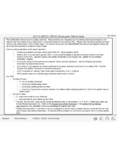
1 -A L L I NO U T 2500/3500 PICKUP AUXILIARY SWITCHES02/17/ 2014 Ram 2500/3500 vehicles have 5 AUXILIARY SWITCHES . These SWITCHES are integrated into the vehicles electrical architecture (LINsignals) with their outputs found underhood in connectors located on the AUXILIARY PDC. Please note that these SWITCHES are hardwired to only switch power (12V) via their relays. The vehicle comes with a kit 68209998AB that contains all required mating halfterminals and connections to allow for ease of is a brief explanation of the switch operation: 5 SWITCHES located in the lower switch bank of the I/P all are AUXILIARY (AUX) All AUXILIARY SWITCHES can be programed to be battery or ignition fed, momentary on and save last state in theEVIC.
2 (See programming menu page) Fuse sizes (rating) for the SWITCHES are customer choice via fuse relocations see the Chassis CabUpfitter Schematic for detailed instructions Connections to the SWITCHES are found underhood in the gray connectors attached to the AUXILIARY PDC. Seethe Chassis Cab Upfitter Schematic for detailed instructions. The caps on the aux connectors are used in conjunction with the eight 12 AWG wires from the up fitter wiring kit tocreate the harness plug. Remove the green plug from the cap and insert inch spade terminal on the wire into thecavity on the cap. It will click into place. AUX 5 power output is on the light gray connector underhood on circuit2 Aux PDC Contains 8 fuses 5 - for the AUXILIARY SWITCHES * 1 - for 20 amp Upfitter battery feed* 1 - for 20 amp Upfitter ignition/run feed 1 - 5 amp mini fuse can be customer located in its holder to allow changing SWITCHES 1 and 2 from ignition feedto battery feed** Houses 6 relays 5 - relays are for the AUXILIARY SWITCHES 1 - relay provides 20 amp Upfitter ignition feed*The 40A, 25A and 20A, fuses can be moved as desired to any of the SWITCHES 1, 2, 3, 4 or 5.
3 These fuse sizes arefor identification purposes only. Refer to the Chassis Cab Upfitter Schematic in the Upfitter Wiring InterfaceInstructions for max. allowable continuous amperage for a given fuse size .+ INDEX MAIN MENURam Trucks | Ram Engineering | AUXILIARY SWITCHES Video -A L L I NO U T02/17/20142500/ 3500 PICKUPAU XI LIA RYS W I T C H E S+ IDEX MAIN MENU 2500/3500 RAM HOME-+02/17/ 2014 ` 2500/3500 PickupAU XI LIARYS W I T C H E SAUX 1PK/WTAUX 3PK/DGAUX 2PK/RDNoConnectAUX 4PK/TNGroundBKPassThroughVT/YLAUX 5PK/VT-Here is the location of the connector with the switch outputs:+