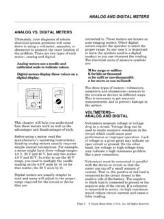
Transcription of 3-1/2 Digit, Analog-to-Digital Converter
1 2008 Microchip Technology 1TC14433/AFeatures: Accuracy: of Reading 1 Count Two Voltage Ranges: and mV Up to 25 Conversions Per Second ZIN > 1000M Ohms Single Positive Voltage Reference Auto-Polarity and Auto-Zero Overrange and Underrange Signals Available Operates in Auto-Ranging Circuits Uses On-Chip System Clock or External Clock Wide Supply Range: to 8 VApplications: Portable Instruments digital Voltmeters digital Panel Meters digital Scales digital Thermometers Remote A/D Sensing SystemsDescriptionThe TC14433 is a low-power, high-performance,monolithic CMOS 3-1/2 digit A/D Converter . TheTC14433 combines both analog and digital circuits ona single IC, thus minimizing the number of dual slope A/D Converter provides automaticpolarity and zero correction with the addition of twoexternal resistors and two capacitors.
2 The full scalevoltage range of this ratiometric IC extends millivolts to volts. The TC14433 canoperate over a wide range of power supply voltages,including batteries and standard 5-volt TC14433A features improved performance overthe industry standard TC14433. Rollover, which is themeasurement of identical positive and negativesignals, is specified to have the same reading withinone count for the TC14433A. Power consumption ofthe TC14433A is typically 4 mW, approximately one-half that of the industry standard TC14433/A is available in 24-Pin PDIP, 24-PinSOIC (TC14433 device only), and 28-Pin PLCC packages.
3 Package TypeNote 1:NC = No internal connection (In 28-Pin PLCC).2:24-Pin SOIC (Wide) package, only for TC14433 PDIP (Wide) 24-Pin SOIC (Wide)VREFNCVDDQ3Q1Q0DS2DS3DS1DS4Q2 VAGVXCO1 VEECO2R1/C1C1R1 VSSEOCNCNCNCDUCLK0 CLK119202122232425111098765TC14433/A12 13 14 151718432127 26281628-Pin PLCCOR3-1/2 digit , Analog-to-Digital ConverterTC14433/ADS21394D-page 2 2008 Microchip Technology Application3145678232221201391415 19 18 171611 10 2 12 2442359101112131415176543211011121314151 6 R1*VX20 k DCSRTC14433 QQDCSR+5V-5V16+5V+5 VSegmentResistors150 (7)+5 VQQ-5V-5V-5V-5V8 Minus Sign 200 51 k 67+5V-5V-5V-5 VMPS-A12(4)CommonAnode LedDisplayMPS-A12300RC14013B539111213126 71410fgedcba+5V1 F 48DS4DS3DS2DS1-5 VMCP1525 4543B1413 VINVOUTVSSPlus Sign110 1 F** F** k F50 F*R1 = 470 k for 2V Range*R1 = 27 k for 200 mV Range**Mylar Capacitor 2008 Microchip Technology 3TC14433 CHARACTERISTICSA bsolute Maximum Ratings Supply Voltage (VDD VEE).
4 To +18 VVoltage on Any Pin: Reference to to (VDD + )DC Current, Any Pin: .. 10 mAPower Dissipation (TA 70 C): Plastic PLCC .. Plastic PDIP .. 940 mW SOIC .. 940 mWOperating Temperature Range .. -40 C to +85 CStorage Temperature Range .. -65 C to +160 C Notice: Stresses above those listed under AbsoluteMaximum Ratings may cause permanent damage tothe device. These are stress ratings only and functionaloperation of the device at these or any other conditionsabove those indicated in the operation sections of thespecifications is not implied. Exposure to AbsoluteMaximum Rating conditions for extended periods mayaffect device ELECTRICAL SPECIFICATIONSE lectrical Characteristics.
5 Unless otherwise specified, VDD = +5V, VEE = -5V, C1 = F, (Mylar), C0 = F,RC = 300 k , R1 = 470 k @ VREF = 2V, R1 = 27 k @ VREF = 200 mV, TA = +25 ConditionsAnalog InputRollover Error (Positive) and Negative Full Scale SymmetrySYE-1 +1 Counts200 mV Full Scale VIN -VIN = +VINL inearity Output Reading (Note 1) + + %rdgVREF = 2V-1 count +1 count %rdgVREF = 200 mVStability Output Reading (Note 2)SOR 2 LSDVX = , VREF = 2V 3 LSDVX = 199 mV, VREF = 200 mVZero Output ReadingZOR 00 LSDVX = 0V, VREF = 2 VBias Current: analog InputReference InputAnalog GroundIIN 20 100 pA 20 100 pA 20 100 pACommon mode RejectionCMRR 65 dBVX = , VREF = 2V,FOC = 32 kHzNote 1:Accuracy The accuracy of the meter at full scale is the accuracy of the setting of the reference voltage.
6 Zero is recalculated during each conversion cycle. The meaningful specification is linearity. In other words, the deviation from correct reading for all inputs other than positive full scale and zero is defined as the linearity :The LSD stability for 200 mV scale is defined as the range that the LSD will occupy 95% of the :Pin numbers refer to 24-pin 4 2008 Microchip Technology SPECIFICATIONSD igitalOutput Voltage (Pins 14 to 23) (Note 3)VOL = 0V, 0 Level = -5V, 0 LevelOutput Voltage(Pins 14 to 23) (Note 3) VVSS = 0V, 1 VVSS = -5V, 1 LevelOutput Current(Pins 14 to 23) mAVSS = 0V, VOH = mAVSS = -5V, VOH = 5V SourceOutput Current(Pins 14 to 23) mAVSS = 0V, VOL = mAVSS = -5V, VOL = SinkClock FrequencyfCLK 66 kHzRC = 300 k Input Current -DUIDU 1 APowerQuiescent Current: TC14433A:IQ VDD to VEE, ISS = 0 = 5, VEE = -5 VDD = 8, VEE = -8 Quiescent Current.
7 TC14433 VDD to VEE, ISS = 0 = 5, VEE = -5 VDD = 8, VEE = -8 Supply RejectionPSRR mV/VVDD to VEE, ISS = 0, VREF = 2V,VDD = 5, VEE = -5TC14433/A ELECTRICAL SPECIFICATIONS (CONTINUED)Electrical Characteristics: Unless otherwise specified, VDD = +5V, VEE = -5V, C1 = F, (Mylar), C0 = F,RC = 300 k , R1 = 470 k @ VREF = 2V, R1 = 27 k @ VREF = 200 mV, TA = +25 ConditionsNote 1:Accuracy The accuracy of the meter at full scale is the accuracy of the setting of the reference voltage. Zero is recalculated during each conversion cycle. The meaningful specification is linearity. In other words, the deviation from correct reading for all inputs other than positive full scale and zero is defined as the linearity :The LSD stability for 200 mV scale is defined as the range that the LSD will occupy 95% of the :Pin numbers refer to 24-pin Characteristics: Unless otherwise indicated, VDD = +5V and VEE = RangesOperating Temperature RangeTA-40 +85 CNoteStorage Temperature RangeTA-65 +150 CThermal Package ResistancesThermal Resistance, 24LD PDIP JA C/WThermal Resistance, 24LD CERDIP JA N/A C/WThermal Resistance,24LD SOIC Wide JA 70 C/WThermal Resistance, 28LD PLCC JA C/WNote.
8 The internal junction temperature (TJ) must not exceed the absolute maximum specification of +150 C. 2008 Microchip Technology 5TC14433 PERFORMANCE CURVESNote: Unless otherwise specified, VDD = +5V, VEE = -5V, C1 = F, (Mylar), C0 = F, RC = 300 k , R1 = 470 k @ VREF = 2V,R1 = 27 k @ VREF = 200 mV, TA = +25 2-1:Rollover Error vs. Power Supply SkewFIGURE 2-2:Sink Current at VDD = 2-3:Clock Frequency vs. Resistor (RC)FIGURE 2-4:Quiescent Power Supply Current vs. Ambient 2-5:Sink Current at VDD = 2-6:% Change to Clock Frequency vs. Ambient :The graphs and tables provided following this note are a statistical summary based on a limited number ofsamples and are provided for informational purposes only.
9 The performance characteristics listed hereinare not tested or guaranteed. In some graphs or tables, the data presented may be outside the specifiedoperating range ( , outside specified power supply range) and therefore outside the warranted ERROR (IN LSD) AT FULL SCALE(PLUSE COUNT LESS MINUS COUNT)-3-2-101-4-3-2-1 Typical Rollover Error vs. Power Supply Skew (VDD I-IVEE I) - SUPPLY VOLTAGE SKEW (V)01234234 Note: Rollover Error is the Difference in Output Reading for the same analog Input Switched from Positive to 5-40 C+25 C+85 CTypical N-Channel Sink Current at VDD VSS = 5 VoltsID - SINK CURRENT (mA)VDS - DRAIN TO SOURCE VOLTAGE (VDC)1M10k10k 100k 1M 100kCLOCK FREQUENCY16,400 RATE =Typical Clock Frequency vs.
10 Resistor (RC)ICLK - CLOCK FREQUENCY (Hz)RC - CLOCK FREQUENCY RESISTOR Note: 5% Typical Variation over Supply Voltage Range of to 8 VCLOCK FREQUENCY80 MULTIPLEX RATE =Typical Quiescent Power Supply Current - QUIESCENT CURRENT (mA)TA - TEMPERATURE ( C)01234-40-20020406080100 VEE = -8 VVDD = +8 VVEE = -5 VVDD = +5V0-1-2-30-1-2-3-4-5 Typical P-Channel Sink Current at VDD VSS = 5 VoltsID - SINK CURRENT (mA)VDS - DRAIN TO SOURCE VOLTAGE (VDC)-40 C+25 C+85 C43210-1-2-3-4-40-20020406080 Normalized at 25 C 5V Supply 8V SupplyICLK - CLOCK FREQUENCY (% CHANGE)Typical % Change fo Clock Frequency vs. FREQUENCY16,400 RATE =CLOCK FREQUENCY80 MULTIPLEX RATE =TA - TEMPERATURE ( C)TC14433/ADS21394D-page 6 2008 Microchip Technology DESCRIPTIONSThe descriptions of the pins are listed in Table 3-1:PIN FUNCTION TABLEPin PDIP, SOICPin PLCCS ymbolDescription12 VAGThis is the analog ground.