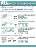
Transcription of 3/16 GLASS FRAMELESS SWING DOOR - Holcam
1 3/16& quot ; GLASS FRAMELESS SWING DOOR. 3. 4. 13. 13. 11 12. 12. 11. 1. 5. 13. 13. 11. 12 8. 12. 11. 13. 13. 4. 11. 12. 12. 11. 2. 6 2. 7. Latch Pack CAT#: PART LIST: QTY.: Parts Bag #3021 PART LIST: QTY.: DOOR ASSEMBLY 1 2196 HANDLE 1. 1268 WALL CHANNEL 2 VS-11 HANDLE VINYL (NOT SHOWN) 1. 1193 STRIKE JAMB 1 2195 HANDLE MAGNET 1. 4002 BULB SEAL IN STRIKE 2. 2217 3/16 WALL ANCHORS 6. 2194 STEEL IN STRIKE 1. 2101 #8 X 1-1/2 FHPHSMS 6. 4082 DRIP RAIL 1 12. 2110 #8 X PH TEK SCREWS 6. 1019 DAM STRIP 1 13. 11-13 Only Parts Bag #3026. Page 1 P/N 6113. TOOLS REQUIRED FOR 3/16 GLASS FRAMELESS SWING DOOR. 1. Rubber or Wooden Mallet 6. Sharp knife or razor knife 2. Hacksaw 7. Drill w/ #2 Phillips tip & 1/8& quot ; and 3/16& quot ; drill bits 3. Level 8. 70% Isopropyl Alcohol & Clean Cloth 4. Mill file for rounding sharp edges 9. Painters tape 5.
2 Caulking gun & Caulk (Clear silicone recommended) 10. Tape measure 1 Mark the centerline of the opening lightly with a pencil. Evaluate your threshold. If an inward slope is not present on your threshold use the Dam Strip. If using the dam strip measure from wall to wall and cut it to 1/16 less than the opening. Install dam strip with the vertical lip to the outside. Before mounting the wall jambs for a door only installation, cut the wall channels down to the same size as the hinge and strike. Position the wall jambs down onto the dam strip or threshold, over the centerline, plumb and mark hole locations. Drill 3/16 holes and install the anchors. Place wall jambs over anchors and secure with #8x1-1/2 screws. Check for plumb and adjust if necessary. Outside 2 Determine which side you would prefer the door to hinge from, usually the side with the shower head.
3 Place the strike jamb over the wall channel opposite the side where the door will hinge. Position the hinge jamb over the remaining wall channel so that the door will open out and secure the at the top with a clamp or #8x1/2 tek screw. Plumb with a level, and adjust the hinge and strike jambs to leave a 3/16 reveal between the edge of the door and the base of the strike jamb from top to bottom. Once the door is plumb and level, secure the top, middle and bottom of the hinge jamb with a #8x1/2 tek screw. WALL REF. WALL REF. 3/16 . 3 Install the handle by placing the vinyl sleeve over the edge of the GLASS lined up with the steel in Flex the handle open and install over the vinyl the strike jamb. Flex the handle open and slide it over the vinyl as far as possible with the magnet on the inside of the door. TIP: Soapy water will help the handle slide over the vinyl.
4 Carefully tap the handle the rest of the way onto the GLASS with a rubber or wooden mallet. Trim off any excess vinyl around the handle. Adjust the strike to work correctly with the magnet in the door handle and to be plumb. Secure the top, middle and bottom of the strike with #8x1/2 tek screws. 8. 4 Measure the bottom of the door from the edge of the GLASS to the hinge rail. Cut the drip rail to that size so that the notch is on the side where the hinge rail is and the flange is on the inside of the shower. Notch the flange of the drip rail so that it does not interfere with the strike on the inside of the door. The flange may be scored with a razor knife to make it easier to snap off. The upper portion of the drip rail should be notched so that the flexible sweep extends under the hinge rail. When you are satisfied with the fit of the drip rail install it onto the bottom of the door pushing up far enough so that the sweep drags across the dam strip.
5 When the rest of the installation is complete, remove the drip rail and place a few drops of silicone into the channel. Replace the drip rail onto the bottom of the door GLASS . TOP VIEW Flange inside of shower Notch for Measure hinge rail Notch for strike Notched out e Flang FRONT VIEW. We recommend filing any sharp corners that may cause injuries, then clean and run a continuous bead of silicone sealant outside of the threshold and up the wall jambs. For installation and technical support please reference the shipping document, the box that the product was shipped in or call the retail location that you purchased the product from. These installation instructions must be followed to ensure proper operation of the door and to reduce the risk of serious injury. Any deviation from these instructions can result in a serious safety hazard !
6 All exposed ends of aluminum that are rough, sharp or jagged due to the metal being cut, drilled or damaged should deburred, smoothed or rounded by the installer before installation. Failure to do so could result in serious injury to the user of the enclosure. Any part of the swinging GLASS door hitting any unprotected bathroom obstruction or metal or GLASS component of the shower door itself, may indicate improper installation and could lead to serious injury. Installer must correct the deficiencies before allowing the door to be used. Page 2 P/N 6113.